Continue to Site

Welcome to our site!

Electro Tech is an online community (with over 170,000 members) who enjoy talking about and building electronic circuits, projects and gadgets. To participate you need to register. Registration is free. Click here to register now.

  • Welcome to our site! Electro Tech is an online community (with over 170,000 members) who enjoy talking about and building electronic circuits, projects and gadgets. To participate you need to register. Registration is free. Click here to register now.

Triac phase triggering

Status
Not open for further replies.

mujid

New Member
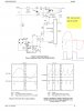
This circuit is from An-3006, but it's not work perfect on me. The upper side of the sinus wave is completelly appear on load,I think it's not suppose to be, But the lower side is correctly triggered .
I'm confusing why the upper side not triggered correctly?
Sorry with the wave form, it's only editted using mouse.
Thanks for helping.
 
Last edited:
Hi,

What circuit are you using?
 
sorry wrong attachemet, here is the circuit :
 

Attachments

  • AN-3006 CIRCUIT3.jpg
    AN-3006 CIRCUIT3.jpg
    138.1 KB · Views: 244
Hi there,


The circuit looks like it should work as is except the thing that strikes me is that there is no triac gate resistor to ground. That could allow the triac to turn on even when it is not supposed to be on, and that looks like what is happening to the upper half of the waveform (it is turning on too soon). The lower half looks like it is working correctly. You can try adding a gate resistor of say 470 ohms and see if that helps. The resistor should connect from the gate to ground.

If that doesnt work we'll have to trouble shoot it a little more, but everything else looks somewhat reasonable.
Of course you should check the timing to the opto input to make sure it is getting turned on at the right time relative to the line voltage.
Also it would be good to know how you are developing your Vcc supply voltage, is it isolated from the line...
 
Have you tried replacing the triac? I've had a few fail where half of it conducts all the time, just like you are seeing there.
 
I'm not see any premature trigger on the scope, I have checked timing waveform from triggering to 555 (pin2) to load waveform, everythink look correct except at the upper side of sinus load.
I have replaced triac and also the opto before I sent this treath but got same waveform, Tomorrow I plan to try mrAI's suggest to add a pulldown resistor on the gate, hoped will help.
 
Today I have try to install a pulldown resistor of 390 Ohms install to the gate and ground but it's not help. one think I found is when I remove the dc supply for the circuit but the upper half sines wave is still fully appear and the lower one is dissapear. It's mean the upper half sines is always triggered and the lower is correct. I don't have any connection between low and high voltage circuit . it's make me more confusing. any idea please.....
 
Hello again,


Well you still didnt tell us how you are developing your Vcc supply voltage. We need to see that.

It could be something very basic like a short or something.

Try using a battery for the Vcc supply voltage and see if that helps. If it does, we really need to see your Vcc supply circuit.
 
Last edited:
Try removing R8 to make sure it is off. If yes replace and remove R6. Off?
Vcc for the 555 and the opto are the same??
 
@mrAi : the dc supply is absolutely, electrically isolated from the TRIACS circuit.

@ronv : Remove R8 make the lmp flickering, but i'm not check yet the waveform
remove R6 give same symptom when I remove the dc supply.
 
OK, so the LED side is not the problem the triac side is. The flickering when you remove R8 could be noise triggering. Mr. Al's resistor to ground may turn it off?? Is it possible you have a very sensitive gate triac? Maybe try the sensitive gate circuit shown in the appication note and keep the gate wires away from all others.
 
Status
Not open for further replies.

New Articles From Microcontroller Tips

Back
Top