Electro Tech is an online community (with over 170,000 members) who enjoy talking about and building electronic circuits, projects and gadgets. To participate you need to register. Registration is free. Click here to register now.
Welcome to our site! Electro Tech is an online community (with over 170,000 members) who enjoy talking about and building electronic circuits, projects and gadgets. To participate you need to register. Registration is free. Click here to register now.
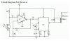
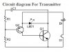
i have problem with my transmitter and receiver circuit. This is my transmitter and receiver circuit diagram. Can someone give another or similar circuit diagram that can work and run correctly. Please.
This is the problem that mr.audioguru told me.
--The circuits that you found on Aaron Cake's site or on a copy-cat site do not work. I fixed the receiver many years ago but I can't remember fixing the transmitter. Nothing limits the current in its IR LED which will probably blow up.
Look at the 100k to 1M missing resistor to ground at pin 3 of the opamp that is supposed to bias its input at the reference voltage of 0V.
The opamp is 50 years old and is not available anymore. Newer opamps will work better.--
mr ezwan, the pt2272/2262 are only ICs to help applications which are ON/OFF. I suppose if you're looking for data transfer, then you'll need better ICs.
The operation is very simple, for the pt2262, there are 4 inputs, any inputs which holds HIGH/ON, the output will also be HIGH/ON at the pt2272's end. If there are 4 switches, ABCD as input let's say, and 4 LEDs at the output of the pt2272, abcd as output for instance, then if you press B, b turns on. Press AC, LEDs ac turns on.
As for your application, you need to describe more on what are your plans, then I can give more input since I'm not sure what you really want.
This site uses cookies to help personalise content, tailor your experience and to keep you logged in if you register.
By continuing to use this site, you are consenting to our use of cookies.