QuickStrike
New Member
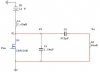
I just want to establish a link to transmit 2MHz to receiver side using a class E amp.
I build the class E amp and I have put a 2MHz squarewave signal from the signal generator into Vin and I'm getting good oscillation at Vo, however this does not mean that my amp is operating under the class e conditions.
How can I check using the oscilloscope if my amp is a class e amp?, i.e. at which nodes of the circuit do I look at using the oscilloscope?
The Lo is the coil or antenna.