Electro Tech is an online community (with over 170,000 members) who enjoy talking about and building electronic circuits, projects and gadgets. To participate you need to register. Registration is free. Click here to register now.
Welcome to our site! Electro Tech is an online community (with over 170,000 members) who enjoy talking about and building electronic circuits, projects and gadgets. To participate you need to register. Registration is free. Click here to register now.
Transistors do not have resistance. They have a base-emitter diode and when it is forward biased with enough current then the transistor conducts current between its collector and emitter.
Every digital multimeter is different. My Fluke multimeter has only 200mV for its OHMS testing which is not enough to make a silicon junction conduct. It has a DIODE TEST which has a few volts which causes a silicon junction or LED to conduct.
I assume you are referring to the emitter-base diode and base-collector diode measured in the forward direction. Those diodes do have resistance, but it varies with the amount of current existing in the diode or the amount of voltage across the diode. They do not obey Ohm's law, and are said to be nonohmic. But their resistance can always be determined by the always correct resistance formuila V=IR at a particular current or voltage. That is why different ohmmeters will give different resistance values for a diode. The voltage the meters use to measure the resistance varies, and therefore the resistance value differs from one model of meter to the other.
I simply look at the datasheet of the transistor to see which pin is which. European BCxxx transistors have the E and C backwards from 2Nxxxx American transistors. Japanese transistors sometimes have the collector as the middle pin.
The emitter-base diode might measure slightly differently from the collector-base diode but I haven't tried it.
He said, "what the use of byepass capicitor in voltage divider bias of transistor."
He did not mention the emitter. He also did not mention a bypass capacitor (because of his poor spelling).
Usually the base of a transistor is biased from a voltage divider, and does not have a bypass capacitor unless it is a common-base amplifier.
You are right in common emitter across emitter resistance, my teacher say to reduce voltage drop across resistance in high freq. but i don't know why they have connected if losses occur..?
The AC voltage gain of a transistor is the collector resistor value in parallel with the load resistance divided by the unbypassed emitter resistor value in series with the internal emitter resistance. The emitter bypass capacitor bypasses the emitter resistor creating a very low impedance for high frequencies which will have high voltage gain.
You can calculate the frequency where lower frequencies have less gain because of the reactance of the bypass capacitor.
You cannot.. This is the diode-equivalent of a NPN trans. --|<--b-->|-- where 'b' = base. So with a DMM you can find the base, that's it. Transistors with metal on the housing (BD139, 2n3055, etc...) always connect the metal to the collector so the 3th pin is the emittor. If you have a plastic casing you'll need a trans.tester (is these days on every DMM). Connect the trans. (you already know the base) and readout the gain (Hfe) switch collector and emittor and read-out the gain again. When the gain is at the highest level your transistor is connected correctly and therefore you found the pin-layout. Hope this helps,Grtz...
The emitter resistor is part of the correct DC biasing of the transistor. The capacitor is added in parallel with the resistor to increase the gain of the transistor at frequencies higher than its calculated cutoff frequency.
Didn't your teacher teach you how to use a simulation program?
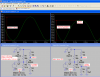
Here is a transistor that is properly biased. Without a emitter bypass capacitor its gain is 9 and its distortion is low. With an emitter bypass capacitor its gain is about 180 but since there is no negative feedback the distortion is extremely high.
i have been using this method for some time: the collector-base terminal has more resistance than the emitter-base junction. It works for both NPN AND PNP
I was just wondering..why trying to find out something you can easely find on the net? In the last few years I didn't encounter a single transistor who's datasheet I didn't find on the net...so why trying to measure it?
This site uses cookies to help personalise content, tailor your experience and to keep you logged in if you register.
By continuing to use this site, you are consenting to our use of cookies.