Continue to Site

Welcome to our site!

Electro Tech is an online community (with over 170,000 members) who enjoy talking about and building electronic circuits, projects and gadgets. To participate you need to register. Registration is free. Click here to register now.

  • Welcome to our site! Electro Tech is an online community (with over 170,000 members) who enjoy talking about and building electronic circuits, projects and gadgets. To participate you need to register. Registration is free. Click here to register now.

Transistor switching - odd behavior at different voltages

Status
Not open for further replies.

rackley

New Member
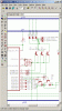
I'm using transistors to switch external loads for my PIC project. I'm using NPN transistors (specifically these: **broken link removed**) with the PIC's output pins connected to the base of the transistors. I have a base resistor of 10k, which I know is too high but that's not my problem. The load it is switching is NOT 5v - it's about 14-15v (automotive relays eventually, but still on the bench right now.) It's actually switching the GROUND for the device, not the power. So the emitter is tied to the ground plane and the collector goes to the screw terminal to be connected to the device's ground wire.

When I test it using the regulated 5v on-board, the transistors completely turn on/saturate to 5.00v, and turn off to 0.00 volts. But if I use my volt meter on the ~14v supply voltage, it turns on/saturates fully to about 14.8 volts, but it only "turns off" to about 6.38 volts. Why is it still letting through 6 volts with a 14/15v load but totally turning off for a 5v load? The PIC pin is low at 0.00v measured - so the transistor base is getting no voltage or current. It seems to be "leaking" through the transistor despite being turned "off." Any ideas?
 
It is not clear what do you mean by saturate. When transistor is in saturation it has minimum Vce, it is ON. When it is OFF it's collector voltage equals supply voltage. To measure this voltages you must connect real load in series with collector and 14V supply. If there is no load, only voltmeter, the reading when transistor is off is wrong. This is because of transistor leakage current Ice0. It is in the range of voltmeter current.
So connect load and measure.
 
Turns out that wasn't it. I connected a relay as the load for the collector circuit and the relay actuated and stayed actuated (the transistor base is turned on/off every 5 seconds by the PIC). Measuring the voltage across the relay yields 9.31v when the transistor's base is on and 9.20v when it is off.

Any ideas as to what the heck is going on here? Why is voltage flowing through these transistors so freely?
 
rackley said:
Turns out that wasn't it. I connected a relay as the load for the collector circuit and the relay actuated and stayed actuated (the transistor base is turned on/off every 5 seconds by the PIC). Measuring the voltage across the relay yields 9.31v when the transistor's base is on and 9.20v when it is off.

Any ideas as to what the heck is going on here? Why is voltage flowing through these transistors so freely?

I take it you do have a reverse connected diode across the relay coil?, if not that could well be the source of your problems? - the transistor will most probably be destroyed the first time the relay turns OFF.

Check the 'Hardware Extras' section of my tutorials, which show how to drive a relay from a PIC.
 
Yes, I have a 1N4004 connected to protect the transistor. I don't have the diode across the relay itself though, I have it on the PCB board.

I actually just read your example schematics, and it's exactly how my circuit is configured, which is why I'm scratching my head.

It works exactly as expected (switches completely on and off) if I use my voltmeter to test with the on-board voltage regulator's 5v power output, the same power that powers the PIC. It goes from +5.00v to 0.00v, measured from the +5v at the voltage regulator to the collector of the transistor. But when I try using the +14v supply that supplies the board, voltage regulator, relay coil, etc, everything gets all funky. Without the coil it goes from about +14v to +6v, with the coil it goes from 9.31v to 9.20v.
 
I think it's time for you to post a schematic showing exactly how you wired the circuit, including the 0V for the two supplies connected together.

Double-check the pins on the transistor. It sounds like you swapped emitter and collector resulting in a zener diode when it is off.
 
Here is part of the schematic that shows 3 of the transistor/diode pairs. Please note the eagle part # for the transistors are not correct, I just used them because they had the right package and electrical schematic and didn't feel like reinventing the wheel just so the label would be right :)
 

Attachments

  • trans_214.gif
    trans_214.gif
    33.8 KB · Views: 837
Are the 0V of both supplies connected together?
Did the transistors ever get hot?
How much current does the load use, what is its resistance?
 
Hello,

But when I try using the +14v supply that supplies the board, voltage regulator, relay coil, etc, everything gets all funky. Without the coil it goes from about +14v to +6v, with the coil it goes from 9.31v to 9.20v.

Where do you measure exactly those voltages? Is it a dropping on the +14v supply line or Vce?
 
The emitter and collector pins of the transistors are probably reversed. I bet-cha. :lol:
 
Hey guys, I didn't get a chance to do much with it last night as real life interrupted :) The coil load measures 96-100 ohms. The grounds of both circuits are connected, and the transistor does seem to get a LITTLE warm, but certainly not hot.

Emitter and collectors reversed - entirely possible. ARGH! Just checked the datasheet for the transistor and the E and C are backwards of what I thought they are. That explains it! That should fix my problem, at least until I move to driver arrays :)

Thanks everyone!
 
I toldyaso! :wink:

Backwards transistors make a pretty good zener diode when the emitter-base junction has avalanche breakdown at about 6V or 7V. Then it is in series with a forward-biased base-collector junction.
Some transistors actually have a little current gain when backwards. :lol:
 
Status
Not open for further replies.

Latest threads

Back
Top