Continue to Site

Welcome to our site!

Electro Tech is an online community (with over 170,000 members) who enjoy talking about and building electronic circuits, projects and gadgets. To participate you need to register. Registration is free. Click here to register now.

  • Welcome to our site! Electro Tech is an online community (with over 170,000 members) who enjoy talking about and building electronic circuits, projects and gadgets. To participate you need to register. Registration is free. Click here to register now.

Transistor question

Status
Not open for further replies.

bigal_scorpio

Active Member
Hi to all,

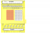
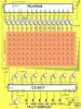
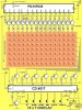
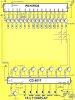
Just a quickie, in the diagram below he used Cathode Rows and Anode Columns.

The only matrixes I have are Cathode Column Anode Rows, could I simply upturn all the transistors and swap the pos and neg to them?

It seems possible but I wanted a bit of confirmation on it, Will it work?

Al
 

Attachments

  • 7x5.JPG
    7x5.JPG
    116.7 KB · Views: 217
hi Al,
The signals will be in reverse voltage sense, so it will not work.
It sinks the cathode end and drives the anode ends of the LED's
 
hi Al,
The signals will be in reverse voltage sense, so it will not work.
It sinks the cathode end and drives the anode ends of the LED's

Hi Eric,

I meant if I changed the circuit as below, but you need to imagine that the matrix is also upside down, I couldn't flip it in paint. doh

Al
 

Attachments

  • 7x5new.JPG
    7x5new.JPG
    116.3 KB · Views: 213
hi Al,
If you mean like this, then by adjusting the base resistor values, you should be able to drive your leds.

I would say that the program for the PIC would need to be re-written to suit.
 

Attachments

  • 7x5new.JPG
    7x5new.JPG
    89.7 KB · Views: 178
Last edited:
Hi Eric,

Yes thats how I meant, the only snag in swapping seems to be RA4 that is to +5 on the original so I put that to its own +5.

What do you mean about rewriting code? Would there be a problem with any of the program? It looked like a straightforward upturn of transistors to me and I thought that would mean the program wouldn't even notice?

As for the resistors wouldn't they still be the same? They will still be passing the same current?

Thanks Al
 
hi Al,
Do you have an image or d/s to show the way that your LED matrix is internally connected.?

I have not studied the program in detail, if a Ian suggests the original author has made some provision for inversion.????
 
Al did you get the software? there was a point in the software that would invert the output signals!

Cheers Ian

Hi Ian,

Yes thanks mate. Still looking at it, tryinmg to get my head around its workings.

Next thing though is to build the matrix, the pins aon these 5x7s are laid out really strangely! Seems to be random! Why couldnt they have all one side as Col and other as Rows, its really gormless , no pattern to them at all.

Thanks Al

Al,
As you have found, its another 'standard' way of wiring led matrices, thats why I am a little cautious about suggesting a circuit.
Post the led diagram and lets see what they are like....
 
hi Al,
Do you have an image or d/s to show the way that your LED matrix is internally connected.?

I have not studied the program in detail, if a Ian suggests the original author has made some provision for inversion.????

Hi Eric,

Yes I have the DS for the matrix, mine are the 57221 doh! I will it post below. :)

As to the inverting I read it as the message itself would be dark and the remaining leds on.

Thanks Al
 

Attachments

  • CSM-57221 led matrix 7x5.pdf
    224.2 KB · Views: 198
hi,
The point to watch out for is the 4017 as its being clocked as a column 'sink', ie: one at a time, if you switch it to a clocked row 'source' .???

EDIT:
Al,
unless I am having a senior moment, the d/s shows the same matrix config as the original drawing.????

EDIT2:
Oh bugger, I referred to the wrong image on the datasheet............:eek:
 

Attachments

  • Image1.png
    Image1.png
    268.7 KB · Views: 187
Last edited:
Hi Eric,

Maybe you got the wrong end of the stick? I am upturning the transistors and in effect those that were sinking will be scourcing and vice versa then putting in my matrix with its reversed polarity. I don't intend swapping rows and columns, I will still be driving rows with the original row drivers and the columns with the original column drivers, just that the led matrix will be anode at the bottom and cathode at the top. So I should not need to change anything else?

The Pins on the PIC and 4017 will still be turning on an NPN as they did so I assume it will be OK?

Al

hi Al,
I have relooked at the circuit and I would say that you are correct.
Sorry about the mix up earlier, lets know it goes.

Eric
 
Status
Not open for further replies.

Latest threads

Back
Top