Continue to Site

Welcome to our site!

Electro Tech is an online community (with over 170,000 members) who enjoy talking about and building electronic circuits, projects and gadgets. To participate you need to register. Registration is free. Click here to register now.

  • Welcome to our site! Electro Tech is an online community (with over 170,000 members) who enjoy talking about and building electronic circuits, projects and gadgets. To participate you need to register. Registration is free. Click here to register now.

Transistor question

Status
Not open for further replies.

DirtyLude

Well-Known Member
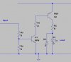
Why does A in the attached schematic work, but B does not? Is it supposed to work and I'm just doing something wrong, or is there a reason it doesn't work.

I'm trying to drive something (not an LED in the example) with switching power, and not switching ground. Full ground is needed to be constant connected while I switch power via PWM.

I know I've done this with a MOSFET in the past, and I could fall back on that, but I don't really have enough drive voltage for a MOSFET.

(I realize that's not exactly the correct symbol fot e TIP120 darlington, but it was just easier this way)
 

Attachments

  • tip120.gif
    tip120.gif
    3.6 KB · Views: 932
Use a PNP to switch the positive line.
connect its emitter to +, and when you apply ground to the base (trough a resistor!) it will connect + to its collector
 
Exo said:
Use a PNP to switch the positive line.
connect its emitter to +, and when you apply ground to the base (trough a resistor!) it will connect + to its collector
For this to work, you need to invert your input signal, and its logic HIGH level needs to be as high as the rail that you are connecting the PNP's emitter to.
Your Darlington emitter follower probably doesn't work because the voltage on the emitter will be about 1.4v lower than your input signal.
 
Either circuit would work with the right choices of V+ and R values. The first cicuit is probably better. Remember, transistors are *current control devices*. Simply put, if you can push a current (in this case) from the base to the emitter, you will get a proportional (hfe) current from the collector to the emitter, if it is in the transistor's capability to do so, by which I mean, once it's saturated, it can't saturate more...

j.
 
John Sorensen said:
Either circuit would work with the right choices of V+ and R values. The first cicuit is probably better. Remember, transistors are *current control devices*. Simply put, if you can push a current (in this case) from the base to the emitter, you will get a proportional (hfe) current from the collector to the emitter, if it is in the transistor's capability to do so, by which I mean, once it's saturated, it can't saturate more...

j.
As I pointed out, the emitter of circuit B will never rise higher than 1.4v below the input HIGH level, regardless of the choice of V+. DirtyLude has said that he doesn't have enough voltage to switch a MOSFET, so he must have less than 5 volts at the input. When you subtract 1.4v for the Darlington emitter follower drop, and around 2v for the LED, there may be not be enough voltage to turn on the LED. As John said, circuit A is probably better in this case.
 
Ron H said:
As John said, circuit A is probably better in this case.
Better, but not useable, like I stated in the first post. The ground needs to be constant, like B, and not switched, like A.

It looks like it will work on the highside if I use a PNP darlington. I have it semi working with a straight PNP transistor right now.

You can see my electronics theory is not very good. Thanks everyone.
 
I wouldn't worry about getting darlington for load that requires
only few miliamp. Btw. TIP120 is a power transistor and huge
overkill for this application. What is driving this circuit? Maybe you
can get rid of thansistor all together...
 
panic mode said:
I wouldn't worry about getting darlington for load that requires
only few miliamp. Btw. TIP120 is a power transistor and huge
overkill for this application. What is driving this circuit? Maybe you
can get rid of thansistor all together...
And how much current are you trying to pass through the LED?
 
In my original message I stated, this is NOT an LED that I'm actually driving. I only used an LED in the example, since it was simple.

I'm actually driving a pair of 12cm fans. See my 'computer fan tach' message. The tach uses ground and if I switch ground to drive the fan, I generate false tach signals.

My solution was to use a resistor to bypass the transistor and always supply the fan with enough minimal current so the tach will work. Unfortunately if I put the resistors on the ground side, the tach signal doesn't get enough ground through the resistors to fully signal.

If I drive the fan on the positive side and supply it with minimal power through a bypass resistor, the tach signal works fine. I'm using a tiny test fan and a small 2n3906 to test and if I leave it on too long, the tiny transistor will burn up.
 
Wow, I missed a bunch of details in the original post :oops:

If you need to switch the high side, you're better off with a PNP. If your driving voltage is not as high as +V (enough to turn off the PNP), you might need another stage.

Why can't you switch the low side? Are you working toward an H-Bridge?

j.
 
In that case this is probably what I would do:
 

Attachments

  • pnp_drive.jpg
    pnp_drive.jpg
    32.4 KB · Views: 621
:lol:
Simply remove the R1 resistor from base of Q1 in case B and will work. So connect base like in your B schematic but directly without R1 resistor.
 
tavib said:
:lol:
Simply remove the R1 resistor from base of Q1 in case B and will work. So connect base like in your B schematic but directly without R1 resistor.

not if he uses a fan like he said he would. IB may become to large without base resistor
 
Tavib, the beta of the TIP120 is a minimum of 1000. If the fan draws 200ma, the base current will be less than 200ua. The resistor is not needed, but it is not the real problem with this circuit. The real problem is as I've already stated: The emitter voltage will be 1.4v less than the input voltage - not the supply voltage, the input voltage.

Exo, this is an emitter follower. The base current is (approximately) equal to the emitter current divided by beta. It doesn't need to be limited by a resistor.
 
panic mode said:
In that case this is probably what I would do:
Hey, thanks. What's the benefit of using this schematic and using a single PNP darlington, like a TIP125?

Actually I don't have any large PNP darlingtons on me, so instead of running both fans off of one transistor, I'll probably duplicate your schematic and drive each fan individually.

I should have been more descriptive in my original message. The input voltage is 3.3v and the fan drive voltage is 12v.
 
:shock:
With 3.3V input voltage the case B schematic of course not work, because you will switch between 0V and 3.3V-1.4V on emitter(1.4V because seem to be a NPN darlington), NOT 0V to 12V as you expected, isn't?

On the other hand, with only 3.3V input, using a PNP is not a good choise because you can't turn off the PNP as it will have E put to +12V and B through limitting resistor at max 3.3V.
 
Status
Not open for further replies.

Latest threads

New Articles From Microcontroller Tips

Back
Top