Continue to Site

Welcome to our site!

Electro Tech is an online community (with over 170,000 members) who enjoy talking about and building electronic circuits, projects and gadgets. To participate you need to register. Registration is free. Click here to register now.

  • Welcome to our site! Electro Tech is an online community (with over 170,000 members) who enjoy talking about and building electronic circuits, projects and gadgets. To participate you need to register. Registration is free. Click here to register now.

Transistor equivalent

Status
Not open for further replies.

Scarr

Member
Hi all,

I need to replace a KTC3875 / KTA1504 PNP transistor I live right next door to CPC | CPC - Over 100, 000 products from one of the worlds leading distributors of electronic and related products. but I can't find one that I "know" will do the job, but this is probably because I'm not that good :) thought I had it when I purchased SC06607 (CPC code) but on my return and after it didn't work I realised the KTC3875 / KTA1504 did have quite a few parameter differences but none I can say "Thats why".

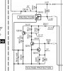
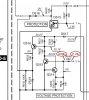
EDIT: P.S. base voltage is +14v (with transistor removed +30v with transistos in place, the service manual says it shoulds be +30v so this all looks good) so the transistor should be switched off yet there is +30v at emitter and collector, with the transitor removed there is 0v at collector pad so I know it's the transistor suppliying the voltage to collector pad, looking at th BCX17 I purchased I think it might not be a good replacment, there are all sorts of parameters that are not the same, I am looking deeper into this but if anyone can point me in right direction it would be a massive help.

EDIT2: right I have looked. checked and tried a second BCX17 I for the life of me don't know why it's not working, I have looked at all the specs, re-checked all the voltages but still no joy! HELLLLPPPPP :)

Thanks for any help in advance.

Steve
 
Last edited:
am I asking

Am I asking a stupid question / impossible question or does my question not make sense?

Quite a few people have read my question but no replies not even a "don't be an idiot" if you do read this and I am being stupid please just say, maybe I cannot see wood for tree's.

thanks

Steve
 
It doesn't seem to be a magic transistor so maybe somethig else is wrong. Can you post your circuit and voltages.
 
Hi ronv

I have attached the service manual, look at p23 and Q515, with the Q515 in place I measure 30v (approx) on all pins BEC it should mesure 30v on B+E as it's a PNP with 0v on C, so I assumed the transistor was faulty, I changed it for a BCX17 but I still get 30v on all pins, with transistor removed I get 14v on B, 30v E, 0v on C and DVR works!

P.S. thanks for answering I thought I was asking a really stupid question or something!

Steve
 

Attachments

  • Kenwood_DVR-8100_service_manual.pdf
    2.8 MB · Views: 636
From the schematic the emitter of Q515 should be connected directly to ground so it should never measure 30 volts. Maybe that trace is open?
 
Hi ronv,

Sorry I gave wrong trasistor number in post, it's Q516 is one I should have said.

Thanks

Steve
 
I have attached the circuit as a jpg

Hi all,

Just to save anyone downloading th PDF I have attached a screenshot of the circuit, Q516 measures 30v at B & C & E when transistor (old KTA1504 or new BCX17) is in place and B = 14v C = 0v E = 30v when transitor is removed.

After D519 it's 5v as expected (with transistor in place)

hope someone point me in the right direction.
 

Attachments

  • circuit.jpg
    circuit.jpg
    92.1 KB · Views: 321
Last edited:
It's hard to tell how this circuit works but it sounds like Q516 would be turned on with the voltages you suggest with the transistor removed. This would imply that Q515 is also turned on (14v @ the base w/o the tx) so you need to trace back from there.
 
Hi ronv (or anyone who can help), OK I probably need to go back to basics here and ask some silly questions, Q516 is a PNP transistor, this transistor will only turn on when B = 0v is this correct? (Q516 was a KTA1504 and had been replaced with a BCX17
If this is correct it is OFF when B > 1.2v approx, in the case of the BCX17, so if I have +30v at base of Q516 (BCX17) then there should be no voltage at output (C) of Q516 as the switch is off.

thanks

Steve
 
Last edited:
Q516 is a PNP transistor, this transistor will only turn on when B = 0v is this correct?
No. it will turn on if the base is less than than emitter by about 0.5 volt


If this is correct it is OFF when B > 1.2v approx, in the case of the BCX17, so if I have +30v at base of Q516 (BCX17) then there should be no voltage at output (C) of Q516 as the switch is off.
You need to quote your voltages with at least one decimal place to determine if The tranny is off or on.

This is a protection circuit and by removing q516 you remove the protection. You need to be careful to not create more damage.

You need to determine if the circuit is defective or if it is doing what it should be doing because there is a defect in the amp output.

With q516 in place, measure the base of q515 to determine if it is detecting a fault. Better still what are the voltages on both sides of its base resistor R648 680 ohms

ADDED Doing a quicky look at the spec sheets on the trannys your bx17 replacement has a base emitter turn on voltage of 1.2 volts and the original kta1504 does not state specifically but a graph shows from 0.4 to 0.7 volts depending on biasing. Of your original, measure the resistance from C to E as well as a diode check for C to E. Switch leads and repeat. You shouldn't get anything if it's good.
 
Last edited:
I think the BC 847 C could be a possible alternative for the KTC3875.
It can switch up to 100mA and have a Breakthru Voltage of 45V.

For the KTA1504 could be the BC 857 C an Reference.

Refer the Datasheets about matching of the parameters and pinning of the Transistors.

EDIT!
Do you know this page: **broken link removed** ?
 
Last edited:
Hi pfofit,

thanks for helping me realise how stupid I was being and why I was getting confused, I have replaced the original KTA1504 (Q516) and measured B+E on Q515, B = 0.70v E = 0.00v, I also measured voltages either side of R648 (see picture)

Thanks for all your help.

P.S. Did not do transistor test as you said as I re-fitted the original transistor and thought getting you these results was going shed more light before I remove it again for testing, also whilst testing I did realise I was disabling the protenction circuit and only ever power up brifely to get readings.
 

Attachments

  • circuit2.jpg
    circuit2.jpg
    95.2 KB · Views: 1,489
Last edited:
Q516 will turn on when the base is about .6 lower than the emitter. The thing that gives it away is that you measure 14 volts on the base with the transistor is removed. This says Q515 is on and it's collector at ground. I think if you measure very carefully you will find that the base is about .6 volts (Vbe drop) lower than the emitter and the collector is about .1 volts higher than the emmitter. Check the voltage on the collector of Q515 and the base of Q515 - also on the other side of the resistor that feeds the base of Q515.
 
Q516 will turn on when the base is about .6 lower than the emitter. The thing that gives it away is that you measure 14 volts on the base with the transistor is removed. This says Q515 is on and it's collector at ground. I think if you measure very carefully you will find that the base is about .6 volts (Vbe drop) lower than the emitter and the collector is about .1 volts higher than the emmitter. Check the voltage on the collector of Q515 and the base of Q515 - also on the other side of the resistor that feeds the base of Q515.
 
Your protection circuit is doing what it should. You have 1.2 volt feeding the base resistor of q515. It should be close to Zero. The 1.2V gives q515 a b-e drop of .7 and this results in a C-E drop of say ~.2 or so, essentially grounding the collector, this then splits 30 volts across the 15k resistors is series, turning on q516 which then gives a c-e drop of ~.2 volt on q516, resulting in 30 volts at the collector.

So you can leave than protection circuit be for now and work backwards to see which amp/s is giving you that 1.2 volts at the base resistor of q515.

Cheers
 
Last edited:
Hi all,

Think I have sorted it but thought it wise to run it by you guys, woking back from the overvoltage protection circuit I found that IC503 (AMP) is outputing 2.32v this can also be mesured on AMP side of R625 and 30.24v at AMP side of R624, so I am going to replace IC503, I did not cut any tracks to test these voltages but ironically when first looking at this I suspected IC503 as the signal going into Q510 was behaving different to the other two AMPS (holding at 5v for a lot longer than ther other to AMPs)

If anyone thinks I am again making too many assumptions or just getting it wrong please please tell me :)

if not thanks for all your help and I will post a reply once the AMP is replaced and hopefully all working.

thanks again

Steve
 
Last edited:
Status
Not open for further replies.

Latest threads

Back
Top