Continue to Site

Welcome to our site!

Electro Tech is an online community (with over 170,000 members) who enjoy talking about and building electronic circuits, projects and gadgets. To participate you need to register. Registration is free. Click here to register now.

  • Welcome to our site! Electro Tech is an online community (with over 170,000 members) who enjoy talking about and building electronic circuits, projects and gadgets. To participate you need to register. Registration is free. Click here to register now.

Transistor Current Consumption

Status
Not open for further replies.

Atmaweapon

New Member
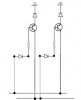
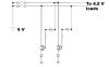
Hey all, quick question. I want to control some LEDs with push button switches but don't want to allow both sets to be on at once. Seems simple enough... I just connected each wire to a transistor as per the diagram so that whenever one switch is pressed, the other switch grounds the circuit.

The problem I'm having is that my LEDs can only handle so much current and I'm having difficulty determining how much current is being diverted by my transistors. If for instance switch 1 is pressed, I assume that transistor 1's base has 0.7 volts applied to it but how much current does that translate to in this state?

Thanks for the help.
 

Attachments

  • AW.jpg
    AW.jpg
    34.1 KB · Views: 169
I don't see any switches in your circuit.
I don't see any loads in your circuit.
Your circuit is drawn upside-down.
 
Didn't post the whole circuit for the sake of simplicity. Load isn't defined yet as it depends on how much I bleed off here. It's a concept question really... is a significant current bled off by a transistor in this state?
 
How is anyone suppose to tell? You didn't include a resistance or voltage or ANYTHING.
 
...

Fine then, here's the entire circuit. 4.5V load across 16 parallel LEDs with an assumed 6V battery series.

As far as upside down, stand on your head if you have to, lol.
 

Attachments

  • JMCircuitDiagram.jpg
    JMCircuitDiagram.jpg
    1.4 MB · Views: 170
Upside-down AND backwards. Great. And appears to be a homework problem. Double-great. And then you cut part of it out, thinking the question could be answered from that. Triple-great. Tell me - did you flip it, too, or did it come that way?
 
It says 24v Where is your 6v.
What is the value of the resistor on the base?
 
Last edited:
Hey Duff, if you don't want to help I understand but no need for all the snark. Been out of college five years and haven't done any circuit design for a bit longer than that - focused more on CS than EE to be honest. Any problems with the diagram are because I'm trying to recreate all of this from the shards of memory I still have of the process.

From what do I remember of EE I have to define my load before I determine the voltages I want to use... in this case I plan to use batteries but whether I go with 4AAs (6V) or a 9V depends on the section I haven't filled in yet because I don't know how much voltage/current is likely to be consumed/diverted.

Each of the 16 LEDs is a bright white that uses 3.2V with 20mA of current, so with the 0.7V diode consumption and the 0.6V resistor consumption each LED branch pulls 4.5V at 20mA.

The values next to the switches are the maximum tolerances of the ones I've purchased; should probably take that off. Sorry about the ugly diagram. Does this new one help at all? Just the conceptual snapshot with 2 switches again.
 

Attachments

  • AW2.jpg
    AW2.jpg
    39.3 KB · Views: 144
Last edited:
Do the switches lock each other out? If they were both on, the transistors would put a short across the battery. Those collectors would be trying to pull the battery voltage nearly to ground. Bad news.

For 20ma, you need to make those LED resistors bigger.

Why don't you show the negative side of the battery in any of these drawings? Is it connected to ground?
 
The switches _don't_ lock each other out simply because they're cheap push buttons and there's 14 of them- is there a relatively easy way to do that myself?

As far as the 20mA issue, each branch is in parallel so they're splitting the current evenly amongst themselves. I do plan to add another resistor in parallel with the battery to drop the total current as needed, but I don't know how much resitance that needs to be yet.

Thanks for your help man.
-J
 
We can't approach a circuit in a "piece-meal" way like this. We have absolutley no idea what you are doing and just like all the other posters, we give answers that are totally off the track and then you say: "we don't know what we are talking about."
 
Last edited:
As far as the 20mA issue, each branch is in parallel so they're splitting the current evenly amongst themselves. I do plan to add another resistor in parallel with the battery to drop the total current as needed,

Sorry, not even close. Take another look at Norton's Theorem.
 
Status
Not open for further replies.

New Articles From Microcontroller Tips

Back
Top