Continue to Site

Welcome to our site!

Electro Tech is an online community (with over 170,000 members) who enjoy talking about and building electronic circuits, projects and gadgets. To participate you need to register. Registration is free. Click here to register now.

  • Welcome to our site! Electro Tech is an online community (with over 170,000 members) who enjoy talking about and building electronic circuits, projects and gadgets. To participate you need to register. Registration is free. Click here to register now.

Transistor Circuit help

Status
Not open for further replies.

pigman

New Member
Hey guys, I'm messing around with a little PWM based project for driving a few LED's in series. I am using a mega168 IC and monitoring current with an LM358 op amp so the program adjusts the PWM to maintain a constant current through an inductor within the restrictions of the LEDs max voltage, etc.

My issue is with the portion that drives the inductor, I've attached what I am using at the moment and I am just a little unskilled in this area with regard to transistor selection and resistor values for safe and long lasting opperation.

It runs input voltage between 12 and 24V

Any help with this will be greatly appreciated
 

Attachments

  • pwm-transistor-circuit.JPG
    pwm-transistor-circuit.JPG
    53.8 KB · Views: 155
Just realised I didn't add info on the output to the leds, voltage is ~11v max and 1-1.5A max nominal should be about 700mA. Also considering replacing the PNP with FZT949 - 30V 3A. Also the PWM runs at 31kHz.

Just after one of you guru's to confirm suggested resistor values and any other addage to protect the gates on the PNP and the NPN also, I've had a couple of the PNP's fail (destroying leds at the same time :( 
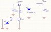
) and just want to ensure I get the gate switched correctly. I tried a 10k resistor on both gates the last time I ran it at 24v and it lasted about 5 minutes before the transistor failed and quickly destroyed the leds, I just wanted to confirm with you guys before I go and potentially destroy another strip of LEDs and a Transistro :(.
 
Last edited:
If you are running 700mA nominal then the peak current through Q1 is probably at least 1A. To completely saturate Q1 the base current should be a least 1/10 of that or 100mA. This means R1 should be (24-1)/100ma = 230 ohms. This resistor will dissipate about 1W average so it should be a 2W resistor.

For 100mA through Q2 its base current should be at least 10mA. This means R6 should be (5-0.7)/10mA = 430 ohms.

Obviously your initial selection of 10k ohm value for the resistors was much too high. Arbitrarily selecting resistor values for a circuit seldom results in satisfactory circuit operation.:rolleyes:

To avoid zapping the leds you might just substitute a low value resistor that draws about the same current and voltage (a 15 ohm, 10W resistor in this case) until you are sure the circuit works properly.
 
Last edited:
crutschow, thankyou for that mate! I guess this is why it operates okish with the 1k resistors at 12v but is getting a bit too hot, certainly wouldn't let it run like that for long.

A quick question, would I be better off switching to a P CH MOSFET ? Would that tend to require less base current? I was looking at this one NDT456P - PCH 7.3A 30V as a potential replacement however I am not sure about the circuitry, I had tried one with a 10k across the base and source and this again worked for a little while but tended to fail.
Do you have any suggestions on circuitry to drive a P CH FET instead?

Cheers
Josh
 
MOSFETs have a gate not a base and they draw no DC gate current. But they do have a significant gate capacitive charge that must be rapidly charged and discharged to switch the transistor on and off rapidly to minimize the switching dissipation. For the NDT456P the maximum gate charge is 67nC maximum. To charge and discharge that is a reasonably fast time of 1us requires a current of 67nC/1us = 67mA. The gate resistor for a 10V gate voltage change should thus be no more than 10V/67mA = 150 ohms. This is actually less then the base resistor I calculated in my previous post.

Thus to rapidly drive a MOSFET gate with minimum power dissipation a push-pull driver (Google totem-pole or push-pull driver) is generally used since it can drive the high current required without dissipating a lot of power.

Another consideration is that the maximum gate voltage is 20V so you must be careful not to exceed that when using a 24V supply.
 
Awesome! steep learning curve, I've also got this P CH Fet handy to work with, looks like it might work better? fdd4243.

I did a bit of testing with LTSpice and this appears to maybe work, see the attached. Would the resistor values be as you've outlined above? and should there be some protection diodes or anything additional in there? or just the pull up/down and thats it?

Thanks again for your help I am learning heaps on this little project!
 
The basic circuit should work as is. Note that the PMW amplitude has to be equal to Vcc to shut off the BC857 PNP.
R3 can be zero or a few tens of ohms (to reduce ringing).

The transistor input resistors can be a few thousand ohms. Their value determines how fast the MOSFET gate capacitance is switched.

One problem with the circuit is that the PWM signal must be a low impedance (never left open). Otherwise the current from the PNP base with also turn on the NPN transistor and there will be short-circuit current through both transistors which could zap them.

If you construct this circuit you must have a very good ground (a ground plane is best) and as short a connection as possible between all devices.
 
ok, awesome! So just a quickly, either of those two selected P CH FETS will work with this?
And they are ok with the fact I will be driving the base on the FET from 0v to 5v only and that the source is from 12- 24v?
The PWM is coming from a ATMEGA PWM pin13(PB1/OC1A) @ 5v, is that ok for the low impedance?

Is there any protection diodes or similar I should throw in there anywhere that would provide some protection from that short circuit situation? Perhaps a resistor from VCC to the 857 to limit current?

PS I got a 10R 10W resistor today for testing :)
 
Last edited:
Sorry, I don't think that circuit will really cut it. Where the input voltage is > Vcc (e.g. 12V in, 5V Vcc), the totem pole output will be either 5V or 0V, the FET VGS = -7 or -12, which will result in an always on FET. Also watch out for the self-destructive nature of that configuration (ie inverting totem pole) - it's possible for both transistors to conduct simultaneously.

I've attached an example level translation schematic if you want to play around with it. It is set up to operate with a ~200kHz PWM source, and requires a logic level drivable FET. C1, R1 & D3 set the gate operating range to roughly between Vin+0.6 to Vin-5. All the other components are to reduce the turn-on surge due to C1 charging and turning on the FET; the inrush can also be decreased dramatically by sending a few pulses of low duty cycle PWM which will get the cap operating where it should very quickly.

You may find 31kHz may be is too low for a small value inductor.

EDIT: a 5V1 or 5V6 zener should be placed on the PWM source for protection from the initial cap charge spike of the circuit I've attached.
 
Last edited:
doug, Thanks dude. yours looks awesome! small volume of parts and all.

All,
I've been messing around and come up with this one that I think might work? What do you think?
 
Scratch that. I simplified it. This is a reverse PWM IE 0v is on and 5v is off.

What do you guys think? It should work yea?
 
Status
Not open for further replies.

New Articles From Microcontroller Tips

Back
Top