Electro Tech is an online community (with over 170,000 members) who enjoy talking about and building electronic circuits, projects and gadgets. To participate you need to register. Registration is free. Click here to register now.
Welcome to our site! Electro Tech is an online community (with over 170,000 members) who enjoy talking about and building electronic circuits, projects and gadgets. To participate you need to register. Registration is free. Click here to register now.
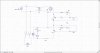
A MOSFET is a transistor that has no current at its gate whether on or off. You could setup a p-channel MOSFET as normally closed, as 0V on its gate would be considered "ON", and positive voltage at its gate would shut it off...
If I turned the battery connected to the gate around wouldnt it short out?(I am planning on using 1 supply.
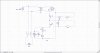
I am not turning a bulb on its a relay that I am switching I just did that simple diagram the one below is what im building,
what should happen is;
For the motor to turn sw1 and sw3 need to be open and sw2 to be closed, if any of the switch is in a different postion(open when it should be closed) the motor will stop and an LED will light turn on, except for D3 which turns on when the motor is running.
I am trying to make this with the minimum amount of component.
What are the voltage and current requirements of your relay coil?
In your schematic, which needs some help, it looks like D3 is on when the motor is on, not D1.
Do you really need all 3 LEDs?
What are the voltage and current requirements of your relay coil?
In your schematic, which needs some help, it looks like D3 is on when the motor is on, not D1.
Do you really need all 3 LEDs?
Sorry yes D3 turns on not D1. the Led's will be mounted away from the switches which are liquid level sensors (float switches) the LED's are to give a quick referrence of which switch is in what state.
The relay requires 12v 35mv
**broken link removed**
If I turned the battery connected to the gate around wouldnt it short out?(I am planning on using 1 supply.
I am not turning a bulb on its a relay that I am switching I just did that simple diagram the one below is what im building,
what should happen is;
For the motor to turn sw1 and sw3 need to be open and sw2 to be closed, if any of the switch is in a different postion(open when it should be closed) the motor will stop and an LED will light turn on, except for D3 which turns on when the motor is running.
I am trying to make this with the minimum amount of component.
If the relay and D3 are energized when the motor is running, then SW1 will be closed, not open as you said. Am I confused, or are you? If it's me, I apologize. If it's you, why don't you try to restate the problem?
If the relay and D3 are energized when the motor is running, then SW1 will be closed, not open as you said. Am I confused, or are you? If it's me, I apologize. If it's you, why don't you try to restate the problem?
Actually I'm new at this and it may not prove to be a problem I'm still a learning. But as is with speakers there is somewhat of a problem with control input when you have mains voltage and I'm just not sure about your circuit we need help.
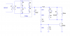
You can use the circuit below if you don't absolutely have to have D1 and D2.
If you need D1 and D2, take a look at the truth table below and correct it, if necessary.
Code:
SW1  SW2  SW3  D1     D2     D3    Motor
O    O    O    off    off    off    off
O    O    C    off    off    off    off
O    C    O    off    off    off    off
O    C    C    off    off    off    off
C    O    O    on     off    off    off
C    O    C    off    off    on     on
C    C    O    on     on     off    off
C    C    C    off    on     off    off
Thanks for that but I relly do need all three LED's, as these will be warning lights, I have rearanged the true table.
Code:
SW1  SW2  SW3  D1     D2     D3    Motor
O    O    O    on     off    off    off
O    O    C    off    off    off    off
O    C    O    on     on     off    off
O    C    C    off    on     off    off
C    O    O    on     off    off    off
C    O    C    off    off    on     on
C    C    O    on     on     off    off
C    C    C    off    on     off    off
The voltage drop of the LED would also allow the transistor to turn on, which is not what you want.
I think the simplest design for you is going to require a 14-pin quad gate package, a couple of transistors, and a few resistors. A microcontroller might require less hardware, but I don't think you have the capability to program one.
I'll work on a design as i have time.
This site uses cookies to help personalise content, tailor your experience and to keep you logged in if you register.
By continuing to use this site, you are consenting to our use of cookies.