Continue to Site

Welcome to our site!

Electro Tech is an online community (with over 170,000 members) who enjoy talking about and building electronic circuits, projects and gadgets. To participate you need to register. Registration is free. Click here to register now.

  • Welcome to our site! Electro Tech is an online community (with over 170,000 members) who enjoy talking about and building electronic circuits, projects and gadgets. To participate you need to register. Registration is free. Click here to register now.

Transistor Amplifier for PWM output

Status
Not open for further replies.

theo92

New Member
Here I'm facing a critical problem to get an amplified PWM signal capable of driving high current loads.

My project is to control brightness of an 3V torch lamp using PWM from 0V to 5V. Then use the ADCs to measure the current draw at various potential differences.

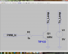
I've programmed the PIC microcontroller and used two buttons, ie. Up and Down to increase or decrease the PWM duty cycles from 0 to 999 (I'm using PIC18F2550 @ 48MHz, PWM freq. 48KHz, duty cycle range = 0 to 999, using PWM writer utility and swordfish) every step of duty cycle increase or decrease, changes the voltage by 0.01. So, it's perfect for my application.

Now, the problem is the PIC's feeble PWM current can't drive the lamp which needs higher current. So, the solution is to use a BJT or FET amplifier. Can someone please suggest me a such amplifier design, preferably using BJT to

* Which can produce ~500mA at 5V
* The output voltage should be exactly same as the input voltage. This is my main requirements as I need a very accurate measurement of current draw at different potential differences. Although I don't know much in BJT basics. I think, it should be an current amplifier with current gain only and no voltage gain. Is it possible? If not possible then a small voltage gain will not be a great problem.

Please suggest me such a design.
 
You want a 5V output which will quickly destroy the 3V lamp.
If the incandescent lamp's operating current is 500mA at 3V then it is 5A when first turned on. Powered by 5V then the lamp will draw nearly 1A when hot and draw nearly 10A when cold.

Use a logic-level Mosfet to drive and to burn out the lamp.
 
You need to limit the PWM duty-cycle to no more than 60% to keep the 3V lamp within its rating from a 5V supply.
 
You want a 5V output which will quickly destroy the 3V lamp.
If the incandescent lamp's operating current is 500mA at 3V then it is 5A when first turned on. Powered by 5V then the lamp will draw nearly 1A when hot and draw nearly 10A when cold.

Use a logic-level Mosfet to drive and to burn out the lamp.

I see I didn't consider it which I should.
Let me explain it a bit more. What I'm actually making is an instrument to verify the Stefan's Law of blackbody radiation. It does measure the current draw of an incandescent lamp at different potential diferences. Then the resistance and power dissipation of the lamp is determined from ohm's law and a calibration curve for tungsten filament. Then log Power vs Log Temp. is drwan is the slope is found to be ≈4. In my college, a device using potentiometers to control the voltage and two displays show the voltage and current. The device is quite old fashioned, bulky etc. I'm making such a device using PIC which will automatically calculate the slope. I'm 60% done, but can't get an idea to drive the lamp.

I was a little wrong. "2.5V 0.35A" is written on the incandescent lamp. Does it mean that it draws 0.35A at 2.5Volt?

In my college, I've performed the experiment using a 9V (maybe 6V, I forget it, I'll check it soon) lamp. It was supplied 0-11.5V using it's internal circuit. It uses two 2N3055 transistors. I've included the data.

But I didn't understand audioguru's reply. Why there be 10Amp when cold. How does a lamp can stay cool when it's powered to it's optimal voltage?

crutschow

You need to limit the PWM duty-cycle to no more than 60% to keep the 3V lamp within its rating from a 5V supply.

I should follow it in a trial and error process. I won't mind destroying a couple of bulbs for it :)
 

Attachments

  • Book1.txt
    4.5 KB · Views: 256
Last edited:
Instead of setting the voltage and measuring the current, you could set the current and measure the voltage. Both are possible, the one yielding the simplest circuit is the best one. Or you could set the voltage to an approximate value, and measure both current and voltage.

You also need to decide if you are going to send a square wave (PWM) current through the lamp (which may pose problems as you will need to filter the measurements), or a filtered current (much easier to measure).

Also, the design's thermal envelope will decide if you can use a linear, or switching, regulation.

Since you probably don't want to pay through the nose for DigiKey shipping to India, some information about the components you can easily have access to would be a plus.
 
Last edited:
"2.5V 0.35A" is written on the incandescent lamp. Does it mean that it draws 0.35A at 2.5Volt?
Yes.

But I didn't understand audioguru's reply. Why there be 10Amp when cold. How does a lamp can stay cool when it's powered to it's optimal voltage?
I didn't know what you are doing with the incandescent lamp so I mentioned that when cold (it is first turned on) its filament is a very low resistance so it draws 10 times as much current as when the filament is at 3000 degrees C when the filament is a much higher resistance. Your driver parts must be able to survive the high current.

I should follow it in a trial and error process. I won't mind destroying a couple of bulbs for it :)
It looks like you are using a little light bulb that was used in an obsolete 2-cells flashlight. Two 1.5V battery cells in series produce only about 2.5V when the current is as high as 350mA. The lightbulb is cheap so its life is short at 2.5V. If you feed it with a voltage higher than 2.5V then it might burn out very soon (in a few seconds?). Maybe you should use a bigger higher quality lightbulb that will last long enough for your measurements.
 
Instead of setting the voltage and measuring the current, you could set the current and measure the voltage. Both are possible, the one yielding the simplest circuit is the best one. Or you could set the voltage to an approximate value, and measure both current and voltage.
Yes. Nice suggestion. But I thought it before. There should be no problem. But Voltage is conventionally taken as independent in most of the cases. So, I also like to use the convention as people are more familiar to see how does the current change with respect to voltage, not the reverse one. The reverse is of course possible and should have no objection, but for ease of use I'd like to set voltage as independent parameter.

You also need to decide if you are going to send a square wave (PWM) current through the lamp (which may pose problems as you will need to filter the measurements), or a filtered current (much easier to measure).
I've used a filter, a two pole low pass filter which can provide an attenuation of 40 db / decade past its cut-off frequency. I've checked it it works nicely, I'm getting steady filtered output.

Since you probably don't want to pay through the nose for DigiKey shipping to India, some information about the components you can easily have access to would be a plus.
Here is Element14, formerly Farnell. Although I didnt bought anything from them. But it's possible to get components from them.
It looks like you are using a little light bulb that was used in an obsolete 2-cells flashlight. Two 1.5V battery cells in series produce only about 2.5V when the current is as high as 350mA. The lightbulb is cheap so its life is short at 2.5V. If you feed it with a voltage higher than 2.5V then it might burn out very soon (in a few seconds?). Maybe you should use a bigger higher quality lightbulb that will last long enough for your measurements.
exactly. It's a lamp from an obsolete flashlight which uses NiMh cells. But it's a really good lamp, as I think it survived my severe torture, I've supplied 6V through it for a couple of seconds, it still unfused and glowed inormously bright. Anyway I'll trial and error those voltage woes. But my main problem still remains unsolved how to provide enough current to the lamp (well, after all I'll limit it to 5V or even less). Logic level Mosfets as told by audioguru. I dont have much knowledge about MOSFETs. Can you please show me some example or explain it a bit. Can it be done using commonly used power transistors? ie. TIP3x or something from 2N serise ie. 2N5296 etc.
 
Last edited:
You can use a TIP31 or 2N5296 if the base current is 35mA (or more if you want the lamp bulb to be brighter than 350mA). But what is the oscillator and what is its output voltage and current?
 
You can use a TIP31 or 2N5296 if the base current is 35mA (or more if you want the lamp bulb to be brighter than 350mA). But what is the oscillator and what is its output voltage and current?

The oscillator is a filtered PWM output from a PIC microcontroller. I've not measured the current. But the voltage varies from 0 to 4.98V.
The PWM is operating at 48KHz which is filtered by a low pass filter and the duty cycle can be varied from 0-100 with 0.1 resolution.
 
This is my solution with the minimum number of parts possible.

Online Sketch: Untitled Sketch by Anonymous Author

The MOSFET is a logic level gate model, with dissipator. The source resistor should be 4 ohms, so at 500mA you have 2V in the resistor, 2-3V in the lamp, and the rest in the MOS.

The PWM sets the current in the lamp to some very unprecise value (but it will increase with an increasing PWM value). After thermal equilibrium is reached (wait a few seconds), the microcontroller takes a number of samples of the points 1,2,3,4 (each filtered by a simple RC) and averages them. This gives you lamp voltage (point 1 - point 2) and lamp current (point 3 - point 4), and you can get a nice curve.

Now, that is an extremely simple way to do it.If you want to set the voltage precisely, you can use an opamp with a source follower, and then you have the problem of measuring the current precisely...
 
This is my solution with the minimum number of parts possible.

The MOSFET is a logic level gate model, with dissipator. The source resistor should be 4 ohms, so at 500mA you have 2V in the resistor, 2-3V in the lamp, and the rest in the MOS.
Then the Mosfet has a Vgs of only 3V and is barely turned on. It needs a Vgs of 4.5V for some Mosfets and 5.0V for other logic-level Mosfets.

The source resistor should have a low voltage drop that is amplified and fed to the microcontroller for it to calculate the average current.
 
Last edited:
This is my solution with the minimum number of parts possible.

Online Sketch: Untitled Sketch by Anonymous Author

The MOSFET is a logic level gate model, with dissipator. The source resistor should be 4 ohms, so at 500mA you have 2V in the resistor, 2-3V in the lamp, and the rest in the MOS.

What's the capacitor for on the mosfet gate? That's just going to slow down the switching time.

What is a dissipator? Pulldown resistor on the gate to discharge it? If not you need something to drain the gate of charge to turn the mosfet off.

Place the current sense resistor on the high side of the mosfet. You'll need to sample it only when the mosfet is on, but that should be no problem. And you'll have to compensate for the slight voltage drop of the mosfet in the readings, but that should also be no problem.
 
> Then the Mosfet has a Vgs of only 3V and is barely turned on.

There are legions of MOSFETs which can be fully turned on with Vgs at 2.5, or even 1.8V. Selecting the right MOSFET saves an amplifier. Using a BJT instead wound include the base current in the current measurement, if the BJT saturates, precision can become pretty bad. But an unsaturated, highish β BJT will do the job too.

> What's the capacitor for on the mosfet gate? That's just going to slow down the switching time.

The MOSFET is used in analog current source mode, so it is not switching. It is a RC to turn a PWM into a filtered DC.

> Place the current sense resistor on the high side of the mosfet.

Yes, you can do that, allowing use of a 5V MOSFET (or a low-β BJT as a dumb current amplifier)

To make the MOSFET switch cleanly at 40 kHz, you'd need a proper driver, Microchip makes some small cheap drivers, but I wanted to propose a solution doable with junk bin parts (although one could say the 2.5V MOSFET doesn't qualify :D but a 1A, high β BJT would) and that doesn't need synchronized sampling (hence the analog filtering).

Another one, this time, much more efficient, and over-engineered, too :

Online Sketch: Untitled Sketch by Anonymous Author
 
Last edited:
Thanks everybody for sharing their suggestions.

Now, a logic level mosfet is unavailable in my place. So, I'm trying to do my job (to control a DC lamp (of 4.5V) from 0V to 5v using PWM from a PIC uC at atleast 0.1V resolution) using NPN darlington transistor TIP122. Will it do my job well?

I've tried the following schematic.

What should be the optimal PWM frequency for this purpose?

In my first test I've failed. My PWM is running at 20KHz. At 1% duty cycle I'm getting 4.63V output and 3.83V at 99% from TIP122 collector. What's wrong with it?

Am I wrong with frequency 20KHz? Is it too high for the TIP122 to turn on and off?
 

Attachments

  • PWM.png
    PWM.png
    181 KB · Views: 449
Last edited:
It could be too high a frequency for the TIP122. Darlingtons are generally rather slow. Why are you using such a high frequency? Try 1kHz or so.
 
Should work, but I have a feeling we are missing something. Can you post a block diagram of your circuit?
 
Yes. I too think we're really missing something.

Now, I've changed something.

Changed the PIC clock freq. to 8MHz instead of 20MHz to generate lower frequency using PWM.

Now using 1KHz PWM frequency with 0-99% duty cycle.

But, anyway my problem is not being solved. still at 1% duty cycle I'm getting 4.97V. At 50% it decreases to 5.08V and it keeps decreasing then with increasing duty cycle, at 63% the output is 5.03V and finally at 99% it is 4.75V. How strange is it.

The PIC is running from a 5v source regulated by 7805 from a 9V battery. And the load is running (I mean what the transistor switching) from a power of 5.7V (meter showing 5.33V) of 1A.

Instead of block diagram, I'm uploading some images of the setup in real world.
 

Attachments

  • basic_setup.jpg
    basic_setup.jpg
    94.8 KB · Views: 274
  • 1percent_duty_c.jpg
    1percent_duty_c.jpg
    87.4 KB · Views: 229
  • 99% duty cycle.jpg
    99% duty cycle.jpg
    598.4 KB · Views: 260
  • 50% duty cycle.jpg
    50% duty cycle.jpg
    87.5 KB · Views: 274
Are the grounds of the two supplies tied together?
Where is your low pass filter?
 
Are the grounds of the two supplies tied together?
Where is your low pass filter?

Yes. The grounds are tied together.
Actually, I've removed the low pass filter. Well, I'll test it adding the low pass filter and then show you the results.
 
Is there a load? Don't forget that "PWM" signal will just peak charge any capacitance on the output and hold it waiting for paracitics to discharge it. You can't just set a certain duty cycle and expect a certain voltage... other considerations come into play.
 
Status
Not open for further replies.

Latest threads

Back
Top