Continue to Site

Welcome to our site!

Electro Tech is an online community (with over 170,000 members) who enjoy talking about and building electronic circuits, projects and gadgets. To participate you need to register. Registration is free. Click here to register now.

  • Welcome to our site! Electro Tech is an online community (with over 170,000 members) who enjoy talking about and building electronic circuits, projects and gadgets. To participate you need to register. Registration is free. Click here to register now.

Transimpedance amplifier

Status
Not open for further replies.

Electrolinux

New Member
Hi, everyone !!

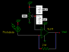
The circuit in the attached file is a transimpedance amplifier or a current to voltage converter. The tricky thing here is that the current is extremely small, some microamperes only, because it is generated by a photodiode, as you can see in the scheme.

When the photodiode is biased (imagine there's no op-amp, so the anode is directly connected to the ground), the photodiode generates a current value which depends on the received light (just the way it should be !!). This current value is very small, as I said above. For example, if the lab has the lights on, the current equals 1.25 :mu: A. If the photodiode lens is covered by a black paper, this current value is only 25 nA. I've realized that the higher the resistor value is, also the higher the current value is. With a 1 K:eek:hm: resistor, there's no any current, so I guess using a 10 G:eek:hm: resistor would be better, but those high value resistors aren't readily available to me.

However, if the converter is added, the photodiode isn't working anymore. The voltage drop in the photodiode is always 0.28 V, which is also the value measured when the photodiode isn't biased. I'd say there are two possible solutions: using an op-amp with a better signal to noise ratio (although the TL071, from T.I., is a low-noise JFET-input op-amp) and using resistors of G:eek:hm: But I don't really know what's going in this circuit whatsoever:confused:

I would appreciate any kind of help. Thank you.
 

Attachments

  • photodiode.png
    photodiode.png
    3.3 KB · Views: 617
Last edited:
Your negative image was a pain to manipulate.

Most opamps won't work if their input voltages are within 2V from a supply voltage. Your opamp had is input connected to its negative supply voltage so that input was turned off.

You can fix it by adding a negative supply, or raising the voltage of the input to within its operating range like I have done.

Your circuit had a resistor in series with the photodiode so the opamp had no gain.

In my circuit, the trimpot adjusts the output voltage when there is no light. Light will cause the output voltage to drop because the opamp is in an inverting configuration.
 

Attachments

  • Photodiode amp.PNG
    Photodiode amp.PNG
    6.7 KB · Views: 843
try the photodiode wizard @ analog devices:
 
Thanks Analog,
That is a nice Photodiode Wizard. I didn't try it because I don't have any spec's for a photodiode but it looks like it uses the photodiode in the photovoltaic mode, like a solar cell for good sensitivity, low noise and good linearity. But it is slow. The reverse-biased photoconductive mode like we are using in this project is much faster.
I wish the Wizard showed a comparison of the two modes.
 
More problems

Thanks to both for your replies, especially to audioguru. The circuit you attached does work, because I built it in a simple protoboard and I checked how the voltage in the feedback resistor is function of the amount of received light. Instead using a variable resistor (as you do in your scheme), I used two fixed resistors: a 330 K one from Vcc (12V) to the op-amp non-inverting input and a 100 K one from the same point to the ground. So the voltage of the non-inverting input is about 2.7 V, more than 2 Volts, as you told me. I'm not using any capacitor by now, but I think I'll use it.
The problem came up when I built this circuit in a board with some soldering. It's not a printed board, is a wrapping board. Right now, although the voltage of the feedback resistor changes with the light, the output voltage is always the same and the voltage of the photodiode isn't as high as it should be. The op-amp chip warms (it didn't happen with the circuit in the other board) and............. Almost sure I have some short-circuit o something like that, but I have double-checked all the connections and...... oh, man, I think this stuff is driving mad! Give me a hint, please.
Thanks a lot
 
Electrolinux said:
Thanks to both for your replies, especially to audioguru. The circuit you attached does work, because I built it in a simple protoboard and I checked how the voltage in the feedback resistor is function of the amount of received light. Instead using a variable resistor (as you do in your scheme), I used two fixed resistors: a 330 K one from Vcc (12V) to the op-amp non-inverting input and a 100 K one from the same point to the ground. So the voltage of the non-inverting input is about 2.7 V, more than 2 Volts, as you told me. I'm not using any capacitor by now, but I think I'll use it.
The problem came up when I built this circuit in a board with some soldering. It's not a printed board, is a wrapping board. Right now, although the voltage of the feedback resistor changes with the light, the output voltage is always the same and the voltage of the photodiode isn't as high as it should be. The op-amp chip warms (it didn't happen with the circuit in the other board) and............. Almost sure I have some short-circuit o something like that, but I have double-checked all the connections and...... oh, man, I think this stuff is driving mad! Give me a hint, please.
Thanks a lot

As you suspect, you very likely have a wiring problem. There is no doubt that the posted circuit works. There really isnt that many parts involved, it shouldnt be tough to find the problem. Triple check all connections and any that look "too close to call", measure with an Ohm-meter to see if they are shorting where they shouldnt be. You'll find the issue in no time.
 
The supply current for a TL071 is 2.5mA or less. Therefore with a 12V supply it heats with only 30mW or less and will not get warm. If its output is shorted to +12V or to ground then its output current will be about 30mA and its heating will be about 360mW which is warm.

The bypass capacitor at the non-inverting input on my sketch keeps the opamp from oscillating at a very high frequency, that might cause it to heat. Install one.

You set its input reference voltage at 2.8V but I told you that is also the output voltage when dark, then light will cause the output voltage to drop. It can go down to about only 1.5V to 2V. If you reverse your input resistors then the output will be 9.2V when dark and drop to 1.5V to 2V when light.

It is difficult to measure the photodiode voltage due to its tiny current in the 2M fedback resistor. A 10M voltmeter's input resistance will cause the voltage to change a lot. It is a transimpedance inverting amplifier with a changing input current, not a changing input voltage.

I haven't seen a wire-wrapped circuit board for about 30 years. In this circuit if an input wire is longer than about 2cm then it will pickup mains hum or cause oscillation at a high frequency. Use a pcb or Veroboard with very short traces.
The power supply terminals on the board must have the supply bypass capacitor I showed, 10uF is fine.
 
audioguru said:
In my circuit, the trimpot adjusts the output voltage when there is no light. Light will cause the output voltage to drop because the opamp is in an inverting configuration.

I built this circuit using a LM358 and a 9V battery as supply. Now the the LM358 has two stages. How could I use the second stage to a) invert this again (if possible) and b) make the circuit more sensitive. My photo-diode is a IF-D91.

It makes pretty big voltage swings when I point the end of my fiber (about 6 ft) to the ceiling light or an LED, but its main application (detecting red squares on an LCD screen) is not working to well. The diodes peak sensitivity is IR, but it has about 50% sensitivity in visible red. Red LEDS work fine.

Thank you so much,
Thomas
 
audioguru said:
Your negative image was a pain to manipulate.
You can invert the colours using MS Paint, if you don't like negative images.
 
Status
Not open for further replies.

Latest threads

Back
Top