Hello Everyone,
I'm going to try and be brief, but there's no assurances.
I've been given some transformer work to do, and have made some headway, but have become stuck.
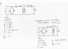
I've been given a transformer equivalent circuit (where R2 and X2) are on the secondary side of the transformer, with values for r1, x1, rm and xm, plus the turns ratio,
I've then converted this into it's further equivalent form by using the referred values for R2 and X2
(I hope your with me so far)
with the transformer operating in no-load and at 415V, I've worked out the primary current, the primary real power, the primary power factor, and the Secondary voltage.
My problem now comes with the transformer supplying a load impedance of (24.16 + j36.69)Ω and again running at 415V...
I need to find the following:
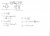
the Primary Current, the Primary Power Factor, the Secondary Current, the Secondary voltage, the secondary apparent power, the secondary real power, the secondary reactive power, the secondary power factor, the efficiency and the voltage regulation.
I'm a little stuck with where to start, and with some of the method.
Any help would be amazing,
Cheers,
Owen.
PS. I've tried to be vague enough so as not to make you guys think I'm asking you to do it for me, but if I've been too vague, please let me know.
I'm going to try and be brief, but there's no assurances.
I've been given some transformer work to do, and have made some headway, but have become stuck.
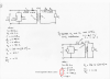
I've been given a transformer equivalent circuit (where R2 and X2) are on the secondary side of the transformer, with values for r1, x1, rm and xm, plus the turns ratio,
I've then converted this into it's further equivalent form by using the referred values for R2 and X2
(I hope your with me so far)
with the transformer operating in no-load and at 415V, I've worked out the primary current, the primary real power, the primary power factor, and the Secondary voltage.
My problem now comes with the transformer supplying a load impedance of (24.16 + j36.69)Ω and again running at 415V...
I need to find the following:
the Primary Current, the Primary Power Factor, the Secondary Current, the Secondary voltage, the secondary apparent power, the secondary real power, the secondary reactive power, the secondary power factor, the efficiency and the voltage regulation.
I'm a little stuck with where to start, and with some of the method.
Any help would be amazing,
Cheers,
Owen.
PS. I've tried to be vague enough so as not to make you guys think I'm asking you to do it for me, but if I've been too vague, please let me know.