Continue to Site

Welcome to our site!

Electro Tech is an online community (with over 170,000 members) who enjoy talking about and building electronic circuits, projects and gadgets. To participate you need to register. Registration is free. Click here to register now.

  • Welcome to our site! Electro Tech is an online community (with over 170,000 members) who enjoy talking about and building electronic circuits, projects and gadgets. To participate you need to register. Registration is free. Click here to register now.

transformer's operation and related concepts

Status
Not open for further replies.

PG1995

Active Member
Hi,

Please have a look on the attachment. Could you please help me with the queries below?

Question 1:
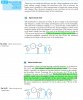
It says under "Open-circuit test":
"The primary current on no load is usually less than 5 per cent of the full-load current, so that the I^2*R loss on no load is less than 1/400 of the primary I^2*R loss on full load and is therefore negligible compared with the core loss."

Where does the factor "1/400" come from?

Question 2:
It says under "Short-circuit test":
"The secondary is short-circuited through a suitable ammeter A2, as shown in Fig. 34.23 and a low voltage is applied to the primary circuit."

Is this "low voltage" direct current? I don't think so. It should be alternating current with the frequency shown on the nameplate of transformer. Could you please confirm it?

I don't understand how such a low voltage could produce full load current.

Question 3:
It says under "Short-circuit test":
"The secondary is short-circuited through a suitable ammeter A2, as shown in Fig. 34.23 and a low voltage is applied to the primary circuit. This voltage should, if possible, be adjusted to circulate full-load currents in the primary and secondary circuits. Assuming this to be the case, the I 2R loss in the windings is the same as that on full load. On the other hand, the core loss is negligibly small, since the applied voltage and therefore the flux are only about one-twentieth to one-thirtieth of the rated voltage and flux, and the core loss is approximately proportional to the square of the flux."

How do you define "full-load current"? Is it the maximum current a transformer withstand before going bad?


Helpful links:
1: http://www.ecmweb.com/basics/article/20897066/the-basics-of-transformer-voltage-regulation
2: http://www.electricalunits.com/short-circuit-test-or-full-load-cu-loss-of-transformer/
3: http://en.wikipedia.org/wiki/Short-circuit_test#Fault_withstand
 

Attachments

  • transformer_open_short_circuit.jpg
    transformer_open_short_circuit.jpg
    442.3 KB · Views: 168
Where does the factor "1/400" come from?

If full load current = 1
5% of full load current = 1/20
W = I^2 R
So (1/20)^2 =1/400

Is this "low voltage" direct current?
No it is AC, we are testing a transformer and we want it to work as a transformer.

I don't understand how such a low voltage could produce full load current.
The ammeter across the secondary is affectively a short circuit, so there will be a large current flowing.
If there was full rated voltage on the primary of the transformer, there would be a very large current in the secondary, the ammeter and the transformer would be damaged.

How do you define "full-load current"?
It is what the manufacturer says it is. Read the rating plate or datasheet.

JimB
 
Thank you, JimB.

I couldn't find a detailed datasheet for a laboratory single phase transformer. I was trying to find information on things like magnetizing current/core loss.

Anyway, let's have a look on this datasheet: https://catalog.triadmagnetics.com/Asset/F10-110-C2.pdf . The picture below has been taken from the datasheet.


transformer_111.jpg


The maximum power deliverable by transformer is 1.1 VA.

It also says that voltage regulation is "25% TYP @ full load to no load".

I was going through this webpage:

"You might assume the transformer's output voltage is highest at no load. It would then make sense that (under loaded conditions) the transformer's resistive and reactive components cause the output voltage to drop below its no-load level. This is a logical assumption, but one that's not necessarily so. Depending on the power factor of the load, the output full-load voltage may actually be larger than the no-load voltage."

How could the output full load voltage be larger than the no-load voltage? Could you please help me with it? Thank you!
 
How could the output full load voltage be larger than the no-load voltage?
I have never come across that situation before.
The article that you gave a link for is obviously on a site devoted to electrical supply systems where they are considering much larger transformers and loads than the transformer in your datasheet.

The article speaks about loads with different power factors, which could be lagging (an inductive load) or leading (a capacitive load).
I can imagine that a capacitive load could form a resonant circuit with the inductance of the transformer which would lead to a higher voltage at the transformer output terminals.
(If anyone else on the forum has better information about this than I have, please let us know).

I couldn't find a detailed datasheet for a laboratory single phase transformer. I was trying to find information on things like magnetizing current/core loss.
Unlikely in the average datasheet for the average small transformer.

JimB
 
Where does the factor "1/400" come from?
Made up. Very low cost transformers have less wire than they should (less turns). This allows more current at no load. These transformers run hot because the current might be not 5% but 25%.
How could the output full load voltage be larger than the no-load voltage?
The full load is lower than no load voltage.
I don't understand how such a low voltage could produce full load current.
Connect the Primary to the power line and short the secondary and bad things happen. I have a variable transformer so I can make low voltage at the power line frequency. To test a short secondary I apply low voltage ac to the primary. This way I can make current limit. Maybe 5 or 10Vac to get full current into a short. (depends on the resistance of the primary & secondary windings. This is a wire test not a core test.
How do you define "full-load current"? Is it the maximum current a transformer withstand before going bad?
Going bad? No. Less than that. Rated current. Some one designed the transformer to run at 4A at 30C room temperature at 50hz (not 60) and run happily for 50 years with only 0.01% of the transformers failing. (totally made up the numbers)
 
Hi again,

Short-circuit test:
The short circuit test in which the secondary is short circuited provides information about winding loss and voltage regulation of the secondary.

"On the other hand, the core loss is negligibly small, since the applied voltage and therefore the flux are only about one-twentieth to one-thirtieth of the rated voltage and flux, and the core loss is approximately proportional to the square of the flux. Hence the power registered on wattmeter W can be taken as the I 2R loss in the windings."
Source: https://www.electro-tech-online.com/attachments/transformer_open_short_circuit-jpg.122039/

Question:
How can the power registered on wattmeter W be taken as the I²R loss in the windings. It could only be taken as the loss in primary winding. Yes, the wattmeter reading would give us the loss in windings only when the reading is multiplied by "2". Could you please help me? Thank you.


Note to self:
Open-circuit test:
The open circuit provides information on core loss. The terms core loss and iron loss mean the same. There are three core losses: eddy current losses, hysteresis losses, and anomalous losses. (Source: https://en.wikipedia.org/wiki/Magnetic_core#Core_loss)

Suppose when no load is connected or open-circuit transformer test shows that 9 watt is core loss at 120 V.

Magnetizing current is the term used to denote the total current that flows into the primary of a transformer when the transformer is energized at a specific voltage and frequency, with the secondary open circuited. Although known as magnetizing current it is actually the combination of the current required to magnetize the core (I1) and the current required to supply the losses in the core (I2). (Source: **broken link removed**)

1577011422640.png


The wattmeter reading shows real power dissipated and that's the core loss. The voltmeter and ammeter give RMS values for voltage and current respectively.

Irms is magnetizing current. It contributes toward real power (i.e. core loss) and reactive power. Real power is converted into work done while reactive power shuffles between the source and load every half cycle.

It can be written that: real power = Vrms*Irms*pf where pf = cos(θv-θi). Therefore, pf=(wattmeter_reading)/(Vrms*Irms), so θv-θi=cos⁻¹(pf)

In an ideal case, core loss would be zero and all power would be reactive for open circuit test because primary is just an inductor and current lags voltage by 90 degrees.

Short-circuit test:
(insert question statement here)
Think like this. In case of a short-circuit test a small AC voltage is applied across the primary winding which is nothing more than inductor. Suppose you apply a small voltage across primary but the secondary is still an open circuit. Only a small voltage would be induced across the secondary and wattmeter reading would be really small because the current in an inductor is I=V/jωL and as 'V' is smaller therefore only a small current would flow.

An inductor resists the flow of current as a result of self-inductance which generates an opposing voltage across its terminals, or informally you can say in order for the current to increase in an inductor, it needs to push against the already present magnetic field around the inductor.

Now when the secondary is short circuited, a huge current flows through the secondary. The current in the secondary generates opposing flux to the primary flux and it results into reduction of voltage across the primary. As the primary voltage reduces, more current flows through primary which means primary voltage once again goes back to its value as the supply voltage. During short circuit test maximum rated current should flow through the primary which means the supply should be able to provide full load current.

Informally, when the secondary is open circuit, a certain amount of current flows through primary. When a load is connected to the secondary, an additional amount of current flows through primary to provide power to the load. How is power transferred from primary to the secondary? Suppose 120 V is connected to the primary and the load connected to secondary consumes 1A at 120 V but initially the secondary side circuit is open. The voltage across secondary would be same as the primary, i.e. 120 V. As soon as the switch is turned on and the current starts flowing through load, the voltage across secondary would go down temporarily but at the same time the flow of current through secondary generates its own flux which runs opposite to that of the primary. This counter flux reduces the net self inductance of primary and as a result more current starts flowing through the primary. This increase in current generates more flux and this flux induces more voltage in the secondary. This would go on until the current has reached its maximum value, 1A, through the load. Actually current in the primary generates flux and this flux gets 'converted' into voltage on the secondary side. The counter flux generated by secondary makes the primary to supply the required power although the flux generated by primary as result of turning on load and counter flux generated by secondary results into net zero flux.

Source: https://electronics.stackexchange.c...rmer-why-is-the-excitation-branch-in-parallel

Helpful links:
1: https://www.quora.com/What-is-magnetization-current-of-transformer
2: https://circuitglobe.com/low-power-factor-wattmeter.html
3: https://www.quora.com/Why-core-loss-is-constant-in-a-transformer
 

Attachments

  • transformer_parasitic.jpg
    transformer_parasitic.jpg
    46.3 KB · Views: 155
Last edited:
When doing a short circuit test,
the secondary winding is shorted by an ammeter (low resistance)
the primary voltage is adjusted to that the secondary current is equal to the full load current of the transformer,
the currents in both primary and secondary windings will now be at their full load values, and so the I^2 R losses in the windings will be the full load values.

The voltage applied to the primary winding will be a fraction of the normal operating value, and so the flux in the core will be correspondingly less than the normal value.
The iron loss is proportional to the square of the flux, and so will be very small compared with the normal operating iron loss.

OK?

JimB
 
Question:
How can the power registered on wattmeter W be taken as the I²R loss in the windings. It could only be taken as the loss in primary winding. Yes, the wattmeter reading would give us the loss in windings only when the reading is multiplied by "2". Could you please help me? Thank you.
I'm assuming this is the question you wanted answered.

I'm also assuming that in a short-circuit test, the output is short-circuited, and the input voltage adjusted to give the nominal output current. Typically the input voltage will be 5 - 20 % of the normal voltage. At that voltage, the iron loss will be very small and is ignored.

The input current with zero output voltage will be very close to the input current at full output voltage with the same output current.

Say we have a 50 W, 10 V transformer running from 250 V, the nominal output current is 5 A. The input current would be 0.2 A if the transformer were 100 % efficient, and little a bit more in a real transformer . In a short-circuit test, the output current is 5 A, and the input current will be close to 0.2 A. Both the primary and secondary currents are near the rated currents, so both the primary and secondary windings will be dissipating power near the maximum, and converting electrical power into heat.

The power dissipated in the secondary winding may not be equal to the power in the primary winding. The two powers will probably be similar in a transformer designed to minimise losses, but they won't be exactly the same.

The heat generated by the windings comes from electrical power, and that electrical power has to come from the supply to the transformer, so will be measured by the wattmeter. If the wattmeter were to show just the primary power, the heat from the secondary winding would be coming from nowhere, which would be breaking the first law of thermodynamics.
 
The heat generated by the windings comes from electrical power, and that electrical power has to come from the supply to the transformer, so will be measured by the wattmeter. If the wattmeter were to show just the primary power, the heat from the secondary winding would be coming from nowhere, which would be breaking the first law of thermodynamics.

Thank you!

You are right that the primary is the source of power for the secondary therefore wattmeter should refelct I^2R losses for both the primary and secondary.
 
Status
Not open for further replies.

Latest threads

New Articles From Microcontroller Tips

Back
Top