Electro Tech is an online community (with over 170,000 members) who enjoy talking about and building electronic circuits, projects and gadgets. To participate you need to register. Registration is free. Click here to register now.
Welcome to our site! Electro Tech is an online community (with over 170,000 members) who enjoy talking about and building electronic circuits, projects and gadgets. To participate you need to register. Registration is free. Click here to register now.
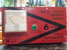
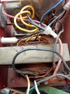
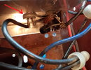
I have an older Torcan 12v battery charger that has a center tap transformer, on the secondary, one wire has 14 volts while the other has only 7.
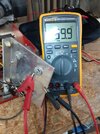
The total output for the charger is only 11 vdc.
Should both secondary wires have 14 volts?
When I take a measurement at the leads that connect to the battery it is 11 volts like it 's splitting the difference between the 14 and 7 volts.
I would think a 12vdc, 6 amp charger should be charging a battery at 14vdc.
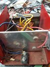
Tested the two rectifier diodes and one is .44nF while the other is .76nF.
One is 88 ohms while the other is 57 ohms.
Would that make much of a difference?
I'm now reading 14 volts on both secondary's.
Tested the two rectifier diodes and one is .44nF while the other is .76nF.
One is 88 ohms while the other is 57 ohms.
Would that make much of a difference?
I'm now reading 14 volts on both secondary's.
What meter range did you use to measure the resistance?
Most modern VOM's cannot test a diode on the resistance range, only the diode test where the diode is forward biased and the volt drop is measured.
You cannot measure the resistance of a diode/rectifier without passing enough forward current.
Which if the result was Kohms then that would confirm it.
The basic transformer - rectifier power circuit is probably like this; the resistor represents whatever load it feeds.
As there is no smoothing capacitor, the output is "rough" DC and a voltmeter will show the average voltage - but the peaks will be rather higher and the battery would take current in pulses at each peak.
If you connect a suitable capacitor across the DC out side, it should allow the meter to read that peak voltage, if needed.
You cannot measure the resistance of a diode/rectifier without passing enough forward current.
Which if the result was Kohms then that would confirm it.
The output is 11 vdc, it was 14vdc a couple of years ago.
I don't think a 12vdc battery will fully charge at 11 volts.
I have 14vac coming from both legs on the secondary.
Measuring 11VDC may be an average, the voltage may have higher peaks. Only a scope would show that. As an idea, try measuring the DC output with the meter in AC voltage setting, it may show the pulse (peak) voltage, but averaged out as well unfortunately.
This site uses cookies to help personalise content, tailor your experience and to keep you logged in if you register.
By continuing to use this site, you are consenting to our use of cookies.