Continue to Site

Welcome to our site!

Electro Tech is an online community (with over 170,000 members) who enjoy talking about and building electronic circuits, projects and gadgets. To participate you need to register. Registration is free. Click here to register now.

  • Welcome to our site! Electro Tech is an online community (with over 170,000 members) who enjoy talking about and building electronic circuits, projects and gadgets. To participate you need to register. Registration is free. Click here to register now.

transfering data via DC power line

Status
Not open for further replies.

ikalogic

Member
Hello.

In a part of a project i am asked to work on, we need to transfer some data (very simple 0/1 informations) via the power lines of a car's battery.

I've made a lot of googling on the net, and i see that it is doable, but can't find and example circuits..

I guess that picking up the information will be done through some kind of high pass filter and tone decoding (or similar approach)

However i have no clue on how to "inject" the data into the power lines..?

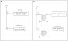
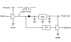
I found this ready circuit, but i don't think it is cheap enough for out application:
DCB500 SPI/UART power-line communication modem transceiver for automotive network

Does anyone here know of some cheap transceiver that can do the job?

any info on the subject is welcome.

thanks a lot.
 
Last edited:
Thanks.. do you think i can attempt to do it my self with caps, op-amps and a micro controller?

do the way of injecting the data via magnetic waves is applicable for DC lines?
 
Looks like they use inductive coupling (i.e. a transformer).

Shouldn't you also be able to use capacitive coupling?
The difficulty with using capacitive coupling is the low impedance of the line. A transformer allows for impedance matching between the driver and the line to generate a larger signal in the line.

This technique can be used to inject a signal into either AC or DC lines.
 
The difficulty with using capacitive coupling is the low impedance of the line. A transformer allows for impedance matching between the driver and the line to generate a larger signal in the line.

This technique can be used to inject a signal into either AC or DC lines.

How can i connect a transformer to DC lines? it'll make a short circuit...? or should i isolate the transformer from the power lines with a capacitor?
 
How can i connect a transformer to DC lines? it'll make a short circuit...? or should i isolate the transformer from the power lines with a capacitor?
Yes, you can block the DC with a capacitor.
 
Is this how it may be done?

i draw that circuit, please tell me if my approach is correct..

Am i missing some important components like diodes or transistors somewhere... (seems like a stupid and ugly question, i know! :D)

Also, i included two versions.. can you tell me which one is better and why..?

and at last, would that work at all?

thanks a lot
 

Attachments

  • tranceiver.jpg
    tranceiver.jpg
    68.7 KB · Views: 730
Last edited:
This idea is fraught with problems due to the noisy nature of the automotive environment. The noise from the alternator and fuel injection systems is horrible. What is wrong with an extra wire? Now if all you are trying to do is have a master device and a slave device and can power the slave from the master with nothing on the power buss between them, then there is a fairly simple way of doing this. Otherwise, the Yanmar product or similar is the way to go since all the complexities are figured out for you.
 
Last edited:
Well i can give it a try and see with a scope how to signals look like.. but can anybody answer my previous post..? thx
 
Well i can give it a try and see with a scope how to signals look like.. but can anybody answer my previous post..? thx

hi ika,
Basically both your circuits are capacitance coupled to the power line.

The power lines are very low impedance and require a low impdance driver, that is, inductive coupling using a transformer.

What frequency are you going to use.?

EDIT:
If you do consider using an 'extra' wire, look at a short fibre optic link from the sensor to main unit.
 
Last edited:
hi ika,
Basically both your circuits are capacitance coupled to the power line.

The power lines are very low impedance and require a low impdance driver, that is, inductive coupling using a transformer.

What frequency are you going to use.?

EDIT:
If you do consider using an 'extra' wire, look at a short fibre optic link from the sensor to main unit.

There are going to be many sensors, so, power line carrier are ideal.. (from an economic point of view)

I am going to use a high frequency.. i guess something in the 500 KHz range..

Don't you think i should use op-amp based high pass filter instead of simple capacitors?
 
There are going to be many sensors, so, power line carrier are ideal.. (from an economic point of view)

I am going to use a high frequency.. i guess something in the 500 KHz range..

Don't you think i should use op-amp based high pass filter instead of simple capacitors?

hi,
I would think that 500KHz is a little high, around 100KHz would be my choice.
A range of prewound transformers [ for mains injection] are available, why not choose a suitable freq transformer.

I would use active filters OPA etc rather than just passive RC filters.
The lines are going to be VERY noisy and would expect some tight filters will be required.
 
Last edited:
aren't there some ICs that handle this task of communicating over DC power lines?

i would be astonished it there wasent.. but i can't seem to find it on the net.. maybe i'm not looking the right place
 
Have you tried Googline "Bias T" circuits? THe data is sent as an AC signal superimposed on the voltage of the DC power line and is AC filtered at the receiving end. A capacitor sits between transmitter and the power line to superimpose the AC data signal onto the DC power, and a capacitor sits between the power line and receiver so the DC gets filtered out and the receiver only sees the AC signal.
 
Last edited:
Thanks.. quite interresting.. (i don't know what happened to google those days, each time you search for something, you get the first 2 pages full of Patents that nobody care about!)

anyway, i found this circuit, can someone help me to modify it to make it work on a car battery instead of AC?
Digital Remote Thermometer
 
anyway, i found this circuit, can someone help me to modify it to make it work on a car battery instead of AC?
Digital Remote Thermometer
You eliminate the power transformers (T1 in each) and and rectifier diodes (D2, D3 and D3, D4) and connect the regulators (IC3 in each) to the battery (through a small resistor and 15V zener to ground to suppress transients).

IC3 in the reciever is a 78L12, 12V regulator, which requires a minimum of 14.5V to work. This regulator will need to be replaced with a 12V low dropout regulator. Alternately the circuit could probably be modified to work with a lower voltage regulator such as a 78L09, 9V device.

hi Carl,
I think what ika is asking is, how to modify the circuit to enable data transmission via the vehicle wiring
rather than the local mains supply.?:confused:

Regards
 
Last edited:
hi Carl,
I think what ika is asking is, how to modify the circuit to enable data transmission via the vehicle wiring
rather than the local mains supply.?:confused:

Regards
Sorry if I wasn't clear. My comments were how to modify it to be powered by the battery which I thought was the main concern.

The signal transformers L1, shown connected to the AC, instead would be connected to 12V power through the cap and to ground (the ground side doesn't need a cap). I assumed that was sort of obvious but I guess it is not.

This scheme may not work as well in a car as with a power line since a power line has balanced wires for the signal and return path. The car has one wire and a chassis return which may muck of the signal some. Only way to know is to try it.
hi,
If it was my project, I would get a car battery on the bench, make up that matching transformer/drive and drive it with a signal generator.

See at which frequencies, if any, the battery offers the highest impedance to the 'ac' test signal.
I think the problem on a car is all that electrical noise from the different systems.
 
i don't know what happened to google those days, each time you search for something, you get the first 2 pages full of Patents that nobody care about!
I really hate that too and it seems that Google Domain filter won't remove them from the list either. Someone is being paid. :rolleyes:
someone help me to modify it to make it work on a car battery instead of AC?
Digital Remote Thermometer
The reason these work well on the 50/60Hz AC line is that the impedance of the power line is relatively high at higher frequencies so it is fairly easy to superimpose a carrier on the AC line.
Compare this to the 12V DC bus of a car where most of the electronics have a capacitor across the DC input which presents a low impedance path to ground for any carrier you try to superimpose.
As I alluded to, and dknguyen stated, the best way is something like this:
 

Attachments

  • Data-Power.PNG
    Data-Power.PNG
    12.6 KB · Views: 548
Status
Not open for further replies.

Latest threads

Back
Top