Continue to Site

Welcome to our site!

Electro Tech is an online community (with over 170,000 members) who enjoy talking about and building electronic circuits, projects and gadgets. To participate you need to register. Registration is free. Click here to register now.

  • Welcome to our site! Electro Tech is an online community (with over 170,000 members) who enjoy talking about and building electronic circuits, projects and gadgets. To participate you need to register. Registration is free. Click here to register now.

Transfer a schematic to a breadboard

Status
Not open for further replies.

zmbs8mytoast

New Member
I am VERY new to this, I found a project that I want to try but I am not sure hoe to go about transferring my schematic to a breadboard. Could somebody please help me out?!?


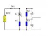
Here is a link to the schematic: **broken link removed**

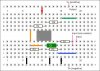
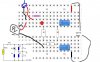
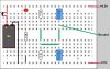
I dont really learn by reading either, so here is a link to a breadboard: **broken link removed**

THANK YOU!
 
Here is one way of doing it.
Note, R2 and R3 could just go straight to the lower power rail saving the outside two black jump wires, I did it this way for clarity.
 

Attachments

  • Breadboardamp.jpg
    Breadboardamp.jpg
    64.5 KB · Views: 508
Here is one way of doing it....y.

Elegant diagram. What did you use to make it?

I would suggest the addition of a Vdd to Vss Bypass Capacitor across the pins of the chip.
 
Elegant diagram. What did you use to make it?
Thanks. I used the second link in the first post. Then I edited it slightly using a generic photo editing type prog'.

Indeed, a bypass cap would be a good idea, I just 'breadboarded' the schematic given.
 
Thank you so much

Thanks! I just got home and saw it, I now understand how it all works out and how to transfer from one to the other, Im going to work out my battery pack for the amp and pot it to see if I get it correct.


Also I will look into adding the cap mentioned, and I will look up what it does

Again, thank you

Jennifer
 
You could go fancy and get software to help you notate the actual breadboard, personally I'd just use a piece of paper and a pencil, pretty easy to move things around that way. After you transfer a few circuits you'll start to get a better idea for how to lay things out on the breadboard, you could make a simple template to print on paper for the breadboard layout itself. Looks like a really good idea to me, never occurred to me before.
 
OK! after checking out the schematic for the amp itself and figuring that out, I think I have the Battery supply figured out, any feedback would be appreciated!

*note, the blue thing is the switch and the gray thing is the battery itself, please excuse the drawing
 

Attachments

  • battery supply.jpg
    battery supply.jpg
    72 KB · Views: 361
The other thing is to just start with the things you cant move, like the pins of the IC, and then start placing resistors, capacitors such that one end is defined by which IC pin it connects to, and the other end is defined by the length of the resistor/capacitor, etc. I have built hundreds of plug-board circuits, and I always just winged it, looking at the schematic, and checking things off as I placed them on the plug board. I never created a drawing of the layout, first....
 
Last edited:
Try to lay out the breadboard like the schematic, it's easier to see if there are mistakes.

The way you have your design, the LED would light, but that's all. Also, one of your capacitors was reversed. I have made a schematic of your design and a breadboard diagram of how it should be.
 

Attachments

  • Breadboard2.jpg
    Breadboard2.jpg
    64.9 KB · Views: 491
  • Schematic1.jpg
    Schematic1.jpg
    15.4 KB · Views: 376
Last edited:
Thanks for your help, I kind of figured out where I was running into some trouble as well, I have a breadboard, but mine doesn't have the two outside rails, for the + and -
 
There is a program called fritzing. It will allow you to input a schematic and get a breadboard look, or vice versa.. it will also render 3d PCBs from the design.

Free and works on most OS's.

Welcome - Fritzing
 
A technique I've used was to draw the schematic on paper, circle the connections in pencil, and identify each connection as a breadboard location. That way, if faults were known then it would be easy to double-check all connections and device polarity. Power connections were identified by red pen for "positive", and black pen for "negative", on the schematic copy.
 
Status
Not open for further replies.

Latest threads

New Articles From Microcontroller Tips

Back
Top