windozeuser
Member
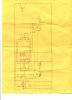
Hey, I was building this circuit (posted below), and noticed that the LED's are not flashing correctly. the first set should start at red, the second set at green, then the second set at yellow, then red. Then the first set goes to green, then it repeats.
R1 = 10K ohm
R3, R4 = 180 ohm
R2 = 500K pot
Q1,Q2,Q3,Q4 = 2n3904 NPN
D1,D2,D3,D4,D5,D6,D7,D8 = 1N914
C1 = 10uF electrolytic
U1 = NE555
U2 = CD4017
D9, D14 = Red LED
D10, D12 = Amber LED
D13, D11 = Green LED
If the Schematic is too hard to read, I'll try to draw it in PCB123
Sorry about the red pen, try to follow the black lines. Plus that 10uF cap in the source(9volts) Is for Filtering, cause my powersupply was a little noisey
Thanks!
P.S The extra LED and 1k resistor connected to pin 3 of the 555 timer was to help me see the pulses.