Continue to Site

Welcome to our site!

Electro Tech is an online community (with over 170,000 members) who enjoy talking about and building electronic circuits, projects and gadgets. To participate you need to register. Registration is free. Click here to register now.

  • Welcome to our site! Electro Tech is an online community (with over 170,000 members) who enjoy talking about and building electronic circuits, projects and gadgets. To participate you need to register. Registration is free. Click here to register now.

Totally stumped by Datasheet! Please Help

Status
Not open for further replies.

bigal_scorpio

Active Member
Hi again to all,

A quick explanation, I'm trying to make a tachometer for my sons lathe with the ICM 7225 counter/display driver.

The LED part of the circuit was no problem and works fine coming on fully lit then counting.

Since I don't understand the data sheet which seems lacking in the usual info, although the sheet says one use of the chip is a tachometer I can't figure out how.

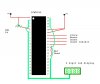
Since experimenting, connecting pin 34 (store) to +V starts the chip counting but, I don't know what its counting and this is with out pin 32 (count) even connected. No where on the data sheet is there a mention of the IC having an internal pulse for it to count!

My pulse would be coming from a spinning disc on the lathe shaft breaking the signal through an opto device. I have inserted a picture of my circuit and the data sheet below, so if you can help me please, please, please do so, I am wracking my brains and already down to less hairs than Homer Simpson.

Thanks for reading this............Al
 

Attachments

  • 7225 circuit.JPG
    7225 circuit.JPG
    44.5 KB · Views: 265
  • ICM7225IPL .pdf
    335 KB · Views: 149
Last edited:
Hi Bigal_scorpio,

It's simple, you need to measure the number of revolutions per second
or per minute. Which means that you also need a timebase to create
an interval where your counter can count the pulses. So you'll need
a reference oscillator, a divider chain and a gate.
Can you give us an idea about how many pulses per second you need
to measure.

on1aag.
 
Pulses per second

Hi On1aag,

Thanks for replying so quickly, the pulses per second right, The disc I will be spinning will have 40 slots in it as I need to measure down to about 50rpm and I thought that 1 slot would make the pulses too long, besides I copied one I saw on a similar lathe ;) they had used 40 slots and the opto sensor the same as mine from a printer, and this was a comercially available kit add on so I figured there must be some reason for the 40 slots! Only difference was they had used a Pic chip and I don't have any or any experience of them yet, I'm trying to learn a bit about electronics before I go that way.

This would mean that the max pulses per second would be 2500rpm divided by 60seconds times 40 slots I think.

Comes out as an odd number though 1666.66666666666 if I'm doing the math right, but I still don't understand what the IC is counting now, and why it will only count when just the STORE pin is connected to V+, connecting the COUNT pin to + or - actually stops the count! Weird or what?

Anyway if you can come up with a working solution I would be forever in your debt, so long as you don't ask me to do a mafia style hit or something ;)

Thanks again..........Al
 
Hi Bigal_scorpio,

One measuring cycle will take 3 seconds to complete but that is due
to the simplicity of the design and the availability of the components.

on1aag.
 

Attachments

  • Lathe rpm counter.GIF
    Lathe rpm counter.GIF
    10 KB · Views: 296
Hi on1aag

Thanks for the circuit mate, but do you mean that it would only sample the RPM every 3 seconds or so?

If so then it may be too big a pause for adjusting the speed, I'm thinking it may take him quite a while to set the lathe to a particular speed if he has to wait 3 seconds after each adjustment?

I have though found another IC that may be more suitable? What do you think? I have posted the Datasheet below.

BTW I can always make another spinning disk that has a different number of slots, even 1 slot if needs be if it made the sampling rate better?

Hope you don't think me ungrateful for the time you spent on the solution you posted, but my son is a real picky little git, (well not so little - 21), and he always finds things to moan about when I make him something so if I can get this spot on I would at last have one up on him! ;)

Anyway let me know what you think of the ICM7217, and thanks again mate.

Regards.............Al
 

Attachments

  • ICM7217BIPI .pdf
    2.9 MB · Views: 188
Changing counter IC's is not going to solve the problem. Any counter to measure frequency, time or in this case RPM accurately needs to have an accurate time base and control circuitry to accomplish this. on1aag has provided a timebase and the control circuitry. The timebase he has shown in effect multiplies the 1666 by 3 to give a true RPM reading. The sample time of 3 seconds can be changed to 0.3 seconds which would give a faster reading. At the moment I don't have a way to change the time to 0.3 seconds, but there are members of this forum that are very good at this.
 
bigal_scorpio said:
Thanks for the circuit mate, but do you mean that it would only sample the RPM every 3 seconds or so?

....................

BTW I can always make another spinning disk that has a different number of slots, even 1 slot if needs be if it made the sampling rate better?

..................................

To reduce the time between readings you have to reduce the time the counter is actualy counting AND increase the number of pulses per revolution (slots in the disk).

The time the counter is actualy counting should be equal to (one minute / the number of slots) to read the speed in RPM.


on1aag's circuit is slow because it has too much "dead times": it is counting only for two seconds (from Q0's pulse to Q3) and uses a full second to latch up the count and reset the counter. (It is counting only 2/3 of the time)

To speed it up you may:
>> use Q7 (pin 6) to reset the FF instead of Q3 (pin 7) (the FF is formed by the two interconected gates)
>> use Q8 (pin 9) to latch the count instead of Q4 (pin 10)
>> use Q9 (pin 11) to reset the counter instead of Q5 (pin 1)
>> Leave the 4017's reset (pin 15) tied to ground instead of Q6 (pin 5)

This way you have an 8 cycles counting period and only 2 cycles of dead time, or 8/10 of the total cycle.

To test your circuit use a 555 as to clock your 4017 (pin 14) at a faster rate (on1aag used 2 hertz). The clock rate mat be obtained as:

Counting time = 60 seconds / number of slots in your disk = 8 clock cycles

Clock frecuency = number of slots in your disk x 8 / 60 seconds.

Later on, the 555 may be replaced with a frecuency divider that uses a cristal oscilator or the main's 50 Hz as a reference.
 
Hi Bigal_scorpio,

I reduced the time of the measuring cycle from 3 to 2 seconds although
the actual measuring time remains at 1,5 seconds.
But for every time you double the number of slots in the disk I could
reduce the measuring cycle to 50 %.
80 slots in the disk 1 second, 160 slots 500ms, . . . 320 slots 250ms
per measuring cycle.

on1aag.
 

Attachments

  • Lathe rpm counter 2.GIF
    Lathe rpm counter 2.GIF
    11.8 KB · Views: 422
Hi again 0n1aag

Just wondered if there would be an upper limit to the speed the counter was capable of clocking if I put say 80 or 160 slots in the disc, I mean would there be a certain speed where the electronics either opto or counter would fail to see pulses, like when you speed up bleeps till there seems to be just one long tone?

After all at 2500 rpm by 160 slots it would mean 400,000 pulses per minute, 6666 per second. Would there be a weak link in the system taht couldn't handle that many pulses? Or are the devices and sensors way faster than I can imagine? Wish I had a scope sometimes hehehe.

Regards and thanks to all..........Al :)
 
Hi Bigal_scorpio,

I think you underestimate the speed of electronic components, you
gonna have a hard time finding one that can't cope with 6666 Hz !
The "weakest" link will probably the opto-interruptor because a
phototransistor is relatively slow.

on1aag.
 
Hi. Your chip's count input is floating. Being CMOS, it will readilly react to random electrical noise, even your AC wiring. Try putting a 10K pullup resistor on each unconnected input pin, as per the data sheet. Also, the data sheet says this chip will handle inputs of 25MHz, which is a 40 nanoseconf pulse! This thing has MORE than enough speed! And it has 500mV hysteresis on the count pin, so slow and/or sloppy signals are not a problem.

BTW, you have a disc with 40 slots, so you'll get 40 'blips' per revolution. So, you're not getting the actual RPM, but, rather, 40 times that! Lots of slots is a good thing on a CNC machine, as each portion of a lead screw's RPM translates to a certain number of thousandths of an inch of travel in the slide. With a lathe, however, you could care less WHERE you are in the rotation. A PIC can sit there and divide the pulses by 40 to determine that one rotation has occured, but the lathe's operator doesn't want to be saddled with the math. I'd say cover 39 of the 40 slots. Then you get just one pulse per rotation.

Next, you need a one second timer. There are TONS of one second counters and timers using the 555 timer IC to be found on the web using a Google search. The problem: how do you set the 555 to one second? You'll need a frequency counter with a period option, or an oscilloscope. There are projects (again, on the web) showing how to use a PC's/laptop's sound input jack as a simple low frequency oscilloscope. These are typically limited to audio frequency speeds, but this is not a problem in this case. Most sound cards are limited to a one Volt input, so you'll have to use a simple volts-divider (two resistors, find this on the web) to get the 555's output down to a usable voltage level.

Hope this helped.
kenjj
 
Status
Not open for further replies.

Latest threads

New Articles From Microcontroller Tips

Back
Top