Continue to Site

Welcome to our site!

Electro Tech is an online community (with over 170,000 members) who enjoy talking about and building electronic circuits, projects and gadgets. To participate you need to register. Registration is free. Click here to register now.

  • Welcome to our site! Electro Tech is an online community (with over 170,000 members) who enjoy talking about and building electronic circuits, projects and gadgets. To participate you need to register. Registration is free. Click here to register now.

TOSHIBA with no vertical drive. M-27AF61 C-TAC0115

Status
Not open for further replies.

mramos1

Active Member
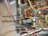
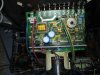
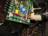
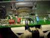
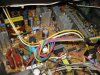
I have a CRT TV I would like to get back in service. My son had it and would tap it and get the vertical to come back on. Figured a bad solder joint. Now it does not come on with his tap, so I have it. Hoping to fix it and use it. Anyone know where the horizontal and vertical output is on the board? Would like to tack all the pads first. Model and Chassis are in the title. I know we have a lot of TV guys on here, Nigel in there too. Thanks for any direction. Mike
 
I am going to bet on the dead chip now. Can you tell me the area to check. There are connectors on the yolk board. I will check them. Is the chip hard to get now? I look at the anode wire and hate working on TVs. But it is a nice set.
 
I am going to bet on the dead chip now. Can you tell me the area to check. There are connectors on the yolk board. I will check them. Is the chip hard to get now? I look at the anode wire and hate working on TVs. But it is a nice set.

Follow the scan coil leads back from the yoke, the frame IC should be mounted on a heatsink near where it connects.
 
This look like the chip. I can hook the scope on it and see what I get if so. I hate that flyback being right there.
 

Attachments

  • tv.jpg
    tv.jpg
    128.4 KB · Views: 518
No, that's the line output transistor - the frame scan coil wires are the right hand two wires on the connector, and presumably go off towards the right, where it's off the picture.
 
Both sets of wires go to a board on the yoke/crt. Here is the board. Hope it is a part on there rather the main board. It is a lot easier to get to. Thanks for the help Nigel.
 

Attachments

  • DSC04602.JPG
    DSC04602.JPG
    140.7 KB · Views: 381
  • DSC04604.JPG
    DSC04604.JPG
    154 KB · Views: 356
  • DSC04605.JPG
    DSC04605.JPG
    146.7 KB · Views: 342
Last edited:
Here is a shot from the back, the connector is lower left. I see 3 heatsinks to the right front. What time is it over there. 8AM here.
 

Attachments

  • DSC04606.JPG
    DSC04606.JPG
    148.1 KB · Views: 354
You see the green and yellow wires on the scan coil plug, follow the rracks underneath to see where they go - I suspect the frame IC is the one on the heatsink to the left of the tuner.

BTW - just gone 1:30PM here.
 
Last edited:
It has been many years since I have working on a TV (tube types). Any clever way to discharge the anode wire so I can remove it. I recall in the old days the CRTs would stay charge for a very long time. Looks like a couple screws and I can pull and plastic slide rail out and start tracing the green and yellow.
 
It has been many years since I have working on a TV (tube types). Any clever way to discharge the anode wire so I can remove it. I recall in the old days the CRTs would stay charge for a very long time.

Take a well insulated screwdriver, attach a wire to it ( just twist around the shaft) attach the other end to a crocodile clip and then clip the croc clip to the spring that is touching the Aquadag coating on the glass of the crt....Slide the blade of the driver up underneath the eht flower......That should discharge the tube's capacitance...

Keep one hand in your pocket should prevent you getting any shock.......
 
It has been many years since I have working on a TV (tube types). Any clever way to discharge the anode wire so I can remove it. I recall in the old days the CRTs would stay charge for a very long time. Looks like a couple screws and I can pull and plastic slide rail out and start tracing the green and yellow.

Can't you get to the bottom of the board without removing the anode cap?.

You're 'supposed' to discharge a CRT through a suitable resistor - but I've always just used two screwdrivers, as do every engineer I know. It wouldn't be any fun without the crack and the sparks :D
 
Can't you get to the bottom of the board without removing the anode cap?.

You're 'supposed' to discharge a CRT through a suitable resistor - but I've always just used two screwdrivers, as do every engineer I know. It wouldn't be any fun without the crack and the sparks :D

Probably can, just the anode makes me nervous. Will get it a shot (not shock I hope).
 
Status
Not open for further replies.

Latest threads

New Articles From Microcontroller Tips

Back
Top