Continue to Site

Welcome to our site!

Electro Tech is an online community (with over 170,000 members) who enjoy talking about and building electronic circuits, projects and gadgets. To participate you need to register. Registration is free. Click here to register now.

  • Welcome to our site! Electro Tech is an online community (with over 170,000 members) who enjoy talking about and building electronic circuits, projects and gadgets. To participate you need to register. Registration is free. Click here to register now.

Toshiba 32" lcd tv 32HL84 power supply problems

Status
Not open for further replies.

CalebG

New Member
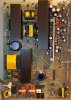
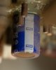
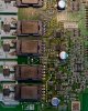
Hi everyone, I have the aforementioned tv, it displays a red standby powerlight but when switched on the set does nothing and the led turns off. I am fairly certain the problem is in the main power board as I am not getting the correct readings on the test pins. There is a 150uf 450v cap that is very slightly bulging in the primary, all the other components looks ok, has anyone else worked on a similar model, if so what did you find? Do you all think that one cap is capable of making the whole thing not function or should I be looking at the transistors as well? I can post pictures if you want to see them. thanks Caleb
 
A photo of what you consider 'slightly bulging' would help; no cap should ever be distended even a little, they're manufactored perfectly flat. I would replace it by default before going any further if it is in fact domed in any way.

The chances of a bad transistor causing the failure are... VERY low; the chances of a cap causing it are VERY high. The cap failure causing another component to fail is highly possible, no reason to conjecture till you post some pics. If it's actually bulging in any way shape or form replace it and try again.
 
Last edited:
Ok here are two pics, one overall and a closeup of the cap in question located near the bottom in the center. I was wondering about the transistors as there is a row of them (MS 7pc123) connecting the primary and secondary.
 

Attachments

  • toshibapowerboard.jpg
    toshibapowerboard.jpg
    173.3 KB · Views: 1,054
  • IMG_1949.jpg
    IMG_1949.jpg
    43.6 KB · Views: 914
thanks for chiming in Nigel, I tested the outputs on the right side of the board as they are labeled for voltages, I get the correct voltages on a few but nothing on the rest. I downloaded the service manual which was very unhelpful as it doesn't go into diagnosing the boards themselves, just says replace. Anything to look for on the main board as common failures?
 
thanks for chiming in Nigel, I tested the outputs on the right side of the board as they are labeled for voltages, I get the correct voltages on a few but nothing on the rest. I downloaded the service manual which was very unhelpful as it doesn't go into diagnosing the boards themselves, just says replace. Anything to look for on the main board as common failures?

The PSU should produce at least one voltage in standby, the main board then sends it a signal turning the rest ON - if it's not been told to turn ON, then you would usually only get 3.3V or 5V, the standby supply for the processor.
 
Well I was getting 5v on a couple outputs, I tore in a bit deeper to look at the main board, found 3 bulging 220uf caps. Pulled and replaced them although when I metered them they all read in the 180-200uf range so I am still looking for the culprit as I don't think the caps were bad enough to cause problems yet. any good tips on testing components on board in the power supply?

on another note , the red led is denoting standby mode the light extinguishes when the power is on but I was able to hear the relays activate when I hit the input button, so portions of the set are getting the correct voltages.
 
Last edited:
Well I was getting 5v on a couple outputs, I tore in a bit deeper to look at the main board, found 3 bulging 220uf caps. Pulled and replaced them although when I metered them they all read in the 180-200uf range so I am still looking for the culprit as I don't think the caps were bad enough to cause problems yet. any good tips on testing components on board in the power supply?

You can't test electrolytics for capacitance, you need an ESR meter - and if they were bulging, they were seriously faulty.

Such problems sometimes cause damage on the main board, due to the HT rails running too high. It's also very likely that other electrolytics on the PSU are faulty - it's also very important that you replace them with good quality 105 degree, low ESR ones.
 
I have a capacitance meter but it only scales to 200uf, I wasn't aware that caps could still read the proper capacitance and have to much resistance, I found a quick easy diy esr meter Equivalent Series Resistance Meter here I going to dig through my parts bin and see if I have the stuff to put it together. It even says you can test most caps on board, thank you very much for the tips and bearing with me.
 
I have a capacitance meter but it only scales to 200uf, I wasn't aware that caps could still read the proper capacitance and have to much resistance.

It's almost always what goes wrong with them, my ESR meter reads both value and ESR, and it's rare for the value to be out of tolerence even though the ESR is sky high.
 
Alrighty then, I built the esr meter, retested and found 9 more bad electrolytics that looked just fine, 2 on the power board and 4 on the main board, and 3 more on the a/v board. Now I have to put it back together and see where to go from there.
 
Last edited:
another quick question, I found a bad .1uf 50v electrolytic, I cant seem to find an electrolytic replacement, I have several 104 ceramic and film caps, but I cant find the voltage ratings for them, I have a few .1 uf 100v electrolytic as well but they all test pretty high on the esr meter (I'm not sure if this is normal or not)? which would be the most suitable?

I went ahead and replaced it with the largest size film cap of that value, and it now works, well sort of, I now am able to turn on the tv and if I stand to the side and push the menu button I can see the menu but I have no backlight, for my next question what is the more common failure the bulbs or the inverter circuit? It does start to light for about 2 seconds from the bottom then blinks off.

update> I went ahead and opened up the panel exposing the inverter board, someone has been here before me as the lead to one of the cfl's was unhooked and the board has seen better days, the second set up was unhooked, but looking at the state of the board I was wondering what caused this to fail? It obviously got quite hot as some of the components are melted. the transformers themselves ohm out as ok but the control circuits are going to need some work.

I tried to resolder the existing components but alas still no backlight, the mosfets that were melted off the board are no longer made, so I may try to get the next closest chip or if I can find a good deal on a replacement board I may have to go that route.

I'm not to familiar with these circuits it tries to power up for about 3 seconds then shuts down I assume something is shorted on the board and the control chip is shutting off the circuit is there a way to test the mosfets with an ohm meter? they are a https://www.fairchildsemi.com/ds/FD/FDS6990A.pdf

I went through and metered all the mosfet legs and found the two that were melted were shorted out, do you think this was caused by the unhooked bulb or did the repair tech unhook the bulb because the mosfets were bad when they worked on it? All the fuses are intact so I am still wondering what caused these two to have a meltdown. how important are the tolerances on these to the micro controller as the replacement chips that are in stock have slightly different capacitance values?
 

Attachments

  • inverter-board.jpg
    inverter-board.jpg
    99.3 KB · Views: 694
Last edited:
Status
Not open for further replies.

New Articles From Microcontroller Tips

Back
Top