Continue to Site

Welcome to our site!

Electro Tech is an online community (with over 170,000 members) who enjoy talking about and building electronic circuits, projects and gadgets. To participate you need to register. Registration is free. Click here to register now.

  • Welcome to our site! Electro Tech is an online community (with over 170,000 members) who enjoy talking about and building electronic circuits, projects and gadgets. To participate you need to register. Registration is free. Click here to register now.

Toroidal Transformer secondary in parallel

Status
Not open for further replies.

Tomek

New Member
Hi

Thats basic question
but I couldnt find answer in other threads

Can I connect Toroidal Transformer secondary in parallel?
I need 9v AC 2-3A
I have Toroidal Transformer 2x9V 30W
Single secondary will give me 9V 15 W - which is about 1.5A (I think Im right?)
connecting both secondarys in paraller should give me 9V about 3 A

If above is correct (Im not fully sure) should it be like diagram A? or diagram B?
(attached pdf)
B does not looks right to me, isnt it short circuiting whole secondary?

Im using few electronics/music devices (multieffects/signal procesors)
all of them are powered by individual 9V AC adapters
- mess on the table and they affect my signal cables (50 Hz hum)
The idea is to get rid of them and use one transformer as master power,
keep it away from signal cables and split it to each device

thanks for help in advance
 

Attachments

  • Diagrams.pdf
    101.4 KB · Views: 345
Im using few electronics/music devices (multieffects/signal procesors)
all of them are powered by individual 9V AC adapters
- mess on the table and they affect my signal cables (50 Hz hum)
The idea is to get rid of them and use one transformer as master power,
keep it away from signal cables and split it to each device
If some of the devices are connected to each other or connected to an amplifier or your computer then you cannot use a common power supply. if you do some can be damaged.
The reason is that not all devices use the negative supply as the return for the output.
 
Distributed regulators from a common source has been around for a long time, thus giving excellent isolation from step currents in crosstalk.

If all the audio equipment uses a bridge rectifier with diode drop to ground, you have to guess which side is grounded. If using an non-isolated SMPS, similar faults can occur.

Check my measuring the AC in to DC voltage drop then ground impedance with power.

Putting transformers in parallel is not OK unless they are identical and have some means of preventing saturation from circulating currents from a mismatch.

Depending on the impedance, a small voltage mismatch can result in a huge circulating current. Usually <1% mismatch is desired. Large circulating current can lead to saturation, which results in one becoming saturated and thus causing more imbalance which results in both getting fried. Higher impedance transformers can tolerate higher mismatch or can be made more tolerant by adding a small ESR to equalize them.

If you are getting a buzz between Audio racks, then Baluns may be needed on the AC input and or LC line filters because diode bridge converters use large peak currents to get low voltage ripple. Worse yet , isolated DC-DC converters in some can pass conducted noise back onto the AC LV input by leakage capacitance and then radiate outward to high impedance sources. High common mode E-fields for high impedance mics can be suppressed at noise source or at signal input by shielding or both.

e.g. when a Laptop charger causes a buzz on an external mic input, one solution is to ground the laptop. Another is a bigger Ferrite Balun on the DC cord or the AC side.
 
Last edited:
Tony thanks for warning
I didnt know that

Putting transformers in parallel is not OK unless they are identical and have some means of preventing saturation from circulating currents from a mismatch.

I understand that potential difference between two not identical secondarys connected in parallel can make trouble
Then what about using both secondarys separately (not connected to each other) as two independent sources of 9v AC?
Can I use one secondary to spread it to 2 or 3 devices and second secondary to another 2 or 3 devices?
The total load of each secondary will not be equal but has it to be?

If you are getting a buzz between Audio racks, then Baluns may be needed

You are right, but in practise I found out that keeping chargers as fare as you can from devices/signal cables does help.
Regardless they are wall warts/AC/DC - they always make hum when too close to signal stuff.
I came to this conclusion by simply moving this stuff in and out and observing hum level
All my chargers AC and DC they have Ferrite Balun

If some of the devices are connected to each other or connected to an amplifier or your computer then you cannot use a common power supply. if you do some can be damaged.
The reason is that not all devices use the negative supply as the return for the output.

moty22 did you mean DC polarisation?
 
moty22 did you mean DC polarisation?
If in one device the output screen is connected to the +9V supply and in another device the input screen is connected to the -9V, when you plug one device to the other you are shorting the 9V supply.

I understand that potential difference between two not identical secondarys connected in parallel can make trouble
If the 2 secondaries are on the same transformer then they are identical. Universal transformers are made to be paralleled.
Only in Canada they make transformers with none identical secondaries, to teach the engineer a lesson. It's the Canadian sense of humour.
 
Last edited:
Tony thanks for warning
I didnt know that

I understand that potential difference between two not identical secondaries connected in parallel can make trouble
Then what about using both secondaries separately (not connected to each other) as two independent sources of 9v AC?
Can I use one secondary to spread it to 2 or 3 devices and second secondary to another 2 or 3 devices?
The total load of each secondary will not be equal but has it to be?
That is OK as there is no crossloading effects with separate transformers . Just verify the common input and output connectivity ( i.e. polarity if diode connection to ground) to avoid internal short on the ones that you pair.
You are right, but in practise I found out that keeping chargers as fare as you can from devices/signal cables does help.
Regardless they are wall warts/AC/DC - they always make hum when too close to signal stuff.
I came to this conclusion by simply moving this stuff in and out and observing hum level
All my chargers AC and DC they have Ferrite Balun

Sometimes the Balun is not big enough, so moving away helps. Sometimes adding a balun with additional shielding to high impedance inputs helps improve CM rejection of E fields. It depends on the rise time or frequency.

moty22 did you mean DC polarisation?

He means the same as I. f all the audio equipment uses a bridge rectifier with diode drop to ground, you have to guess which side is grounded." AC+ or AC- <> diode<> Gnd

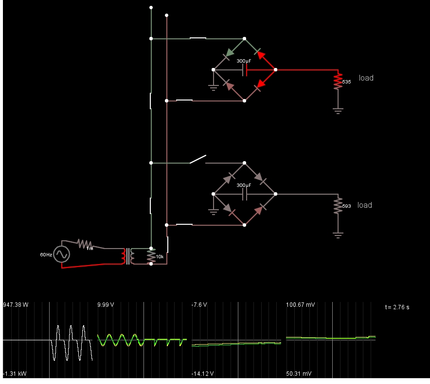
Here is a picture of two units, one with a negative voltage bridge on top and V+ bridge in bottom unit. When both share the same the transformer output, It shorts out then creates a large voltage when removed. Can you see the short?
6024509800_1424981462.jpg
 
Last edited:
Drawing "A" has the secondary windings paralleled (in phase) for double the current of one winding.
Drawing "B" is shorting both secondary windings together (out-of-phase) which overloads the transformer and provides an output voltage of zero.
 
The spec sheet of the transformer should have DOTS on all the windings. Think of this as a polarity symbol. Line them up when in parallel. DOT of one winding to non-DOT of the other when in series.

If you don't know the polarity, connect the identical secondaries in series first. You will either get nearly 0 or 2x the secondary. It's probably easier to visualize the polarities when the the windings read 2x.

so on primary <grey+violet> together and 230 DC between blue and brown
on secondary (to double current) 9V DC between <orange+black> and <yellow+red>
and hopefully both secondaries are identical and there will not be "circulating currents from a mismatch"

Im awaiting for this trafo, once arrived - will test it in practise
 

Attachments

  • DualPrimaryToroidal2x115V-230V.pdf
    691.8 KB · Views: 203
the OP said:
so on primary <grey+violet> together and 230 DC between blue and brown
on secondary (to double current) 9V DC between <orange+black> and <yellow+red>
and hopefully both secondaries are identical and there will not be "circulating currents from a mismatch"

Yes!
 
I have never seen any musical device powered by 9Vac.. always DC

yet you seem to have ALL OF THEM powered by AC.

Why is that?
 
I have never seen any musical device powered by 9Vac.. always DC

yet you seem to have ALL OF THEM powered by AC.

Why is that?

Alesis Nanoverb2 (modern)
Lexicon MPX 100 (old)
Lexicon Alex (old)
x0xb0x (TB 303 clone) (modern)

just to list few of them

and as I spoke earlier with Musicmanager (hi:):
"I use various devices, some of them are new but most are old (vintage)
about half of them are 9v DC other half is 9v AC
which did suprise me because as you suggested I thought oryginally
they are all 9v DC
So I bought 3A 9V DC (wall wart) just to find out that it does only part of my stuff,
lackly it didnt damage those which are AC
and now Im trying this solution with common AC trafo for rest of them"
 
I have never seen any musical device powered by 9Vac.. always DC

yet you seem to have ALL OF THEM powered by AC.

Why is that?
I have seen small audio devices powered by 9VAC. They didn't run the AC through a full wave bridge to make a single 12DC.

One of the AC wires became ground. The other AC wire was connected to two diodes and two capacitors to make +/- 12VDC.

If you have two such devices connected together, you have a 50% chance of shorting something out if they share the same AC wires.
 
The older wallwarts had poor reliability with diodes and caps, but the transformer is essential for noise isolation.
Each unit should be driven by separate secondary winding, unless you know how AC to DC is connected internally with diodes to ensure all shared loads have the same polarity.

Even then, some conducted crosstalk will occur thru shared cap connects.
Use a DMM on diode test mode on both AC inputs relative to Audio ground to verify.

I would tear down each unit to measure its DC requirement and modify all to use shared DC with a CM choke and PTC protection in each. ($0.25)
 
That is OK as there is no crossloading effects with separate transformers . Just verify the common input and output connectivity ( i.e. polarity if diode connection to ground) to avoid internal short on the ones that you pair.


He means the same as I. f all the audio equipment uses a bridge rectifier with diode drop to ground, you have to guess which side is grounded." AC+ or AC- <> diode<> Gnd

Here is a picture of two units, one with a negative voltage bridge on top and V+ bridge in bottom unit. When both share the same the transformer output, It shorts out then creates a large voltage when removed. Can you see the short?
6024509800_1424981462.jpg

so the unit 535 is powered between negative voltage and "zero" while unit 593 between positive voltage and "zero"
(I hope it doesn't take place in my system)
in case like that shouldn't simetrical (+0-) be used?
I think toroidals are made for this purpose
while Im trying to use both toroidal sec's to double current
This theoretically simple idea became quite controversial...
 
Status
Not open for further replies.

Latest threads

New Articles From Microcontroller Tips

Back
Top