Continue to Site

Welcome to our site!

Electro Tech is an online community (with over 170,000 members) who enjoy talking about and building electronic circuits, projects and gadgets. To participate you need to register. Registration is free. Click here to register now.

  • Welcome to our site! Electro Tech is an online community (with over 170,000 members) who enjoy talking about and building electronic circuits, projects and gadgets. To participate you need to register. Registration is free. Click here to register now.

TIP120 / LED circuit

Status
Not open for further replies.

MrDEB

Well-Known Member
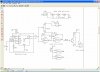
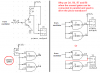
This circuit should work but not real sure if the TIP120 will handle the 48 LEDs
planning on using 12v battery supply.
Calculated using a different website that comes closer to what Audioguru calculates.
LED Resistor Calculator
the site I WAS using seems wrong on all their calcs.
don't use this site?? **broken link removed**
 

Attachments

  • Capture2-6-2009-2.52.38 PM.jpg
    Capture2-6-2009-2.52.38 PM.jpg
    173.6 KB · Views: 962
Pin 2 of the CD4011 will never go high to make the piezo transducer bother everybody because the max base voltage of the TIP120 will clamp the voltage to about 1.3V which is not a logic high voltage.
Pin 2 of the CD4011 will go high if it is connected directly to the output of the 555.

You don't say what is the minimum, typical and max forward voltage of the LEDs for us to calculate their current, if there is any current.
If the LEDs are 3.6V white or blue ones then their max current is ZERO.

Look here:
 

Attachments

  • Mr DEB's circuit.PNG
    Mr DEB's circuit.PNG
    44.2 KB · Views: 1,217
Status
Not open for further replies.

Latest threads

Back
Top