shafri
Member
Hi newbie here. Firstly, sorry if my post got mistakes... I just downloaded TINA-TI from Texas instrument. tried to simulate some stuff, ie mix between TI Chip THS3095 and LM393. Long story short, Tina cannot simulate LM393 behaviour properly. From simulation, i can get LM393 "comparating" at/from 20++ MHz 1Vpp Sine signal. But in the real life circuit, i only can get LM393 stable up to 1.5MHz only. beyond that (2++ MHz), LM393 will simply flattened)
So if i were to trust the simulation, directly make the pcb and solder the components, expecting it to work up to 20++ MHz, i will be in total dissapointment. So any advice from expert here? is this the end of SIM for me? ie just rely on datasheets and make the real circuit right away, and do the debugging later? on the real circuit? or is there still hope for the SIM? any better model available to simulate LM393?
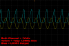
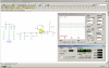
Here is my current LM393 model which i got from TI's site (ti_pspice_models.zip). And i provided the picture of the simulation result (tina.png) vs the real circuit behaviour (real.png) Hope to hear some advice. thanx.
So if i were to trust the simulation, directly make the pcb and solder the components, expecting it to work up to 20++ MHz, i will be in total dissapointment. So any advice from expert here? is this the end of SIM for me? ie just rely on datasheets and make the real circuit right away, and do the debugging later? on the real circuit? or is there still hope for the SIM? any better model available to simulate LM393?
Here is my current LM393 model which i got from TI's site (ti_pspice_models.zip). And i provided the picture of the simulation result (tina.png) vs the real circuit behaviour (real.png) Hope to hear some advice. thanx.
Code:
* LM393 VOLTAGE COMPARATOR "MACROMODEL" SUBCIRCUIT
* CREATED USING PARTS VERSION 4.03 ON 03/07/90 AT 14:17
* REV (N/A)
* CONNECTIONS:   NON-INVERTING INPUT
*                | INVERTING INPUT
*                | | POSITIVE POWER SUPPLY
*                | | | NEGATIVE POWER SUPPLY
*                | | | | OPEN COLLECTOR OUTPUT
*                | | | | |
.SUBCKT LM393    1 2 3 4 5
*
  F1    9  3 V1 1
  IEE   3  7 DC 100.0E-6
  VI1  21  1 DC .75
  VI2  22  2 DC .75
  Q1    9 21  7 QIN
  Q2    8 22  7 QIN
  Q3    9  8  4 QMO
  Q4    8  8  4 QMI
.MODEL QIN PNP(IS=800.0E-18 BF=2.000E3)
.MODEL QMI NPN(IS=800.0E-18 BF=1002)
.MODEL QMO NPN(IS=800.0E-18 BF=1000 CJC=1E-15 TR=807.4E-9)
  E1   10  4  9  4  1
  V1   10 11 DC 0
  Q5    5 11  4 QOC
.MODEL QOC NPN(IS=800.0E-18 BF=20.29E3 CJC=1E-15 TF=942.6E-12 TR=543.8E-9)
  DP    4  3 DX
  RP 3  4 46.3E3
.MODEL DX  D(IS=800.0E-18)
*
.ENDS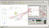
 .
.
 here again i included the test file *.tsc, library *.cir/*.tsm and the main spice macro script *.txt for lm393 (ver 4.03) and lm393x (ver 9.2). i hope that help.