Greetings all,
I am new to this forum, so I will be figuring out protocols as I go. I have an electronics education that I have not used much since I could not find a job in my field after graduation.
Long story short.. that means that now I have a fairly strong understanding of Ohms law (and Kirchoff's) and my algebra is pretty good.
That being said, since some of my questions may sound (read: may actually be) pretty stupid, I should be able to get up to speed reasonably quickly.
What I am working on:
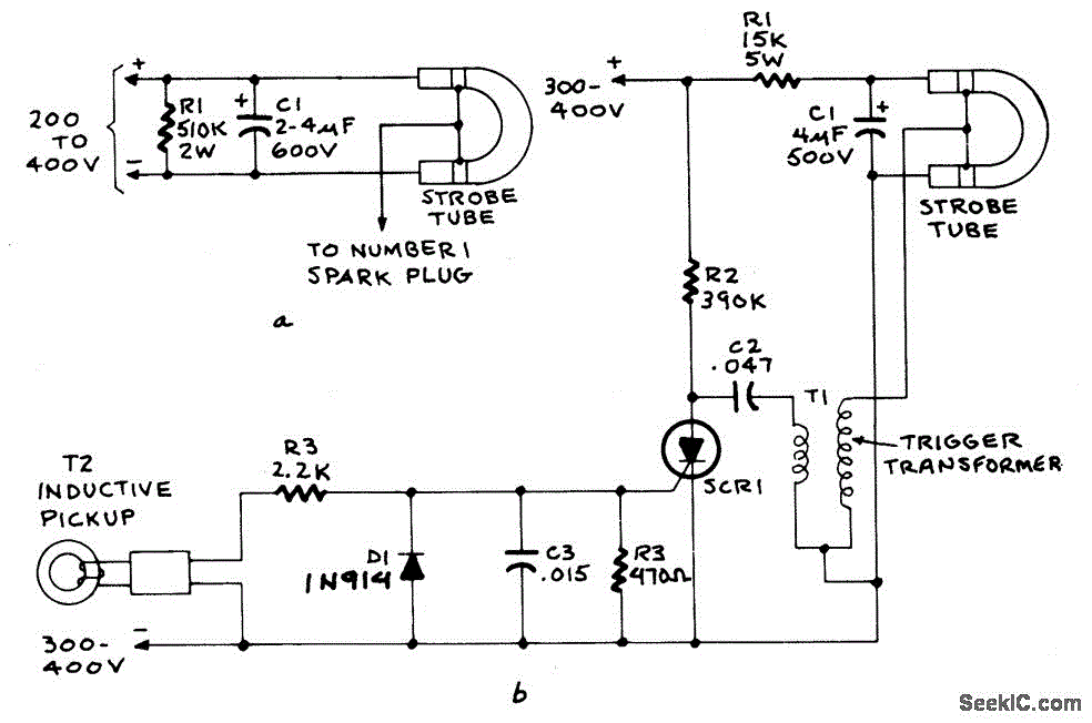
I have a conventional automotive timing light that uses an inductive pickup on the plug wires--high voltage, low current pulse-- that triggers a xenon bulb, and is otherwise powered by the 12VDC car battery.
What I want to do is generate an alternative trigger. I do not have a circuit diagram, nor do I know exactly how these work though I have used them for years.
I have tested the signal coming from the inductive pickup on a scope, and it is a noisy (approx) 2-5 VPP AC spike, sometimes 2 spikes in the uS range. 'Noisy' meaning it looks on the scope just like I feel when I accidentally touch the secondary spark itself.
I have other pickups designed for this and their signal looks the same +/- a little Peak voltage, as the one that is connected to the active circuit.
The reason I am doing this ithat I want a synchronized strobe for something that does not provide me with a 20KV spike to trigger it.
I can provide pictures if that helps, assuming I can figure out how to add them on this forum.
What do you think?


