Continue to Site

Welcome to our site!

Electro Tech is an online community (with over 170,000 members) who enjoy talking about and building electronic circuits, projects and gadgets. To participate you need to register. Registration is free. Click here to register now.

  • Welcome to our site! Electro Tech is an online community (with over 170,000 members) who enjoy talking about and building electronic circuits, projects and gadgets. To participate you need to register. Registration is free. Click here to register now.

timer needed, from perm to pulse

Status
Not open for further replies.

planty

New Member
Hello,
I have a program called circuit wizard and i have about 2 questions,

1, I can make a program work with the 555 chip, but i need the 556 chip and the program wont run/work with it, is there another program better then circuit wizard but is easy yo use, dont think i need a pro level.

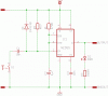
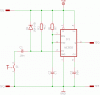
2, I need a small timer kit that works when it is activated by 12v but then has a timed output, using a potentiometer. I have used the kit below but that does a pulse input and a timed output,
**broken link removed**

I would like a non pulse input (i.e. switch it on) and a timed output (again using a potentiometer) which i can put a relay on for a voltage load or a neg load.
Thanks for you help,
 
Hi planty,

the entire circuit is wired as an astable multivibrator with the specified on- and off times.

I guess what you need is a non retriggerable monostable multivibrator, which causes the output to switch a load for a defined time period and return to off after time out.

Is this correct?

Boncuk
 
yep, think thats the one,
with that maplins kit it you keeps resetting itself, i dont want it to reset itself, I have tried all sort of ways but i am only a novice, i can make a maplins kit up and change a few things, and i made 2 pcb boards, but the 2nd one didn't go as planned. as i used 2 555 chips in my computer program as it does understand the 556, but i got a load of pcb made up with 556 so it would be easyer to build.
 
Hi planty,

try this.

The trigger input is pulled high via R2. When S1 is toggled to ground the trigger input will receive a short negative pulse and the output becomes active.

To retrigger the circuit the switch must be toggled off and on again.

Boncuk
 

Attachments

  • NON-RETRIGGERABLE.gif
    NON-RETRIGGERABLE.gif
    7.2 KB · Views: 137
Hello, i have tried to make the circuit but with no luck, Just out of intrest what does T1 - T4 do?
What value is C2 and R1,
Can i put a LED in there so i know when the unit is active/working.

Will try and post a pic below.

**broken link removed**
 
Hi planty,

there are no T1 - T4, but TP1 - TP4. Those are terminals to connect supply voltage and output to the world. ;)

It's quite clear you don't see much reaction of the circuit. If wired correctly the monoflop's time out period is exactly 1.099ms or 0.001099seconds. (R1=1K and C1=1µF) Considering tolerance in capacitance this period might even be shorter.

You can wire an LED (anode) to the output pin (3) in series with a current limiting resistor to ground. The LED is lit as long as the output is active (high), but you won't see and 1ms pulse.

Calculate the resistor like this: R(Ω)=((+UB(V)-Uf(A))/If, where +UB is the supply voltage, Uf is LED forward voltage and If is LED current.

Example: red LED (Uf=1.8V, If=20mA), +UB=12V, put into the formula:
(12-1.8)/0.02=510Ω. 510Ω is not contained in the E-24 restance row, so the next suitable value would be 560Ω. (This will result in an LED forward current of 18.2mA with a negligable loss of brightness.) Never use a lower resistance value than calculated.

Here are values for R1 and C2 for a reasonable time period of 2.427 seconds.
R1=470K, C2=4.7µF. To almost double the time out use R1=820K.

Boncuk
 
Hi again,

here is the altered circuit.

Boncuk
 

Attachments

  • NON-RETRIGG-1.gif
    NON-RETRIGG-1.gif
    8.2 KB · Views: 136
will try the one above in a min.
The kit i am trying to make is,
When a 12v is on it will make a pulse and when the same 12v is off makes another pulse.

When the car engine in on (12v on) then it will send a 12v pulse to lock the car doors, then when the engine is off (same 12v off) it will send a seprate 12v pulse to unlock the doors.
Hope this makes more sence..
 
Hi planty,

it's very clear again you don't see the LED when "lit". Using a 100X greater value for the LED current limiting resistor causes an LED current of 17µA (17 Microamperes), no way to see the LED turned on. The LED current should be about 20mA.

Use the values given in my schematic, and use them as they are printed. The second wrong dimension is the cap across CV (pin5) It should be 10nF - not 10µF!

Why did you hold back important information about the circuit's functions?

Initially you were talking about a circuit swiching an output active for a determined time upon activation. Now it seems the circuit should work under two different conditions.

With the exception of R1 all values are wrong!

Here is the parts list again. Study it carefully and don't select values 10 or 100 times greater than listed. (Your chosen values in paranthesis)

R1 470K (470K), R2 4.7K (4K), R3 560Ohm (560K) **, C1 10nF(10µF), C2 4.7µF (47µF), C3 10nF (10µ)

** Applicable for 12V supply voltage and a red LED. For a supply voltage other than 12V recalculate R3 using the given formula.

Boncuk
 
Last edited:
thanks for the cap thing, changed it, but still cant see the unit working.
any other ideas or kits i could do/make.
 
Status
Not open for further replies.

New Articles From Microcontroller Tips

Back
Top