Continue to Site

Welcome to our site!

Electro Tech is an online community (with over 170,000 members) who enjoy talking about and building electronic circuits, projects and gadgets. To participate you need to register. Registration is free. Click here to register now.

  • Welcome to our site! Electro Tech is an online community (with over 170,000 members) who enjoy talking about and building electronic circuits, projects and gadgets. To participate you need to register. Registration is free. Click here to register now.

timer circuit help

Status
Not open for further replies.

simple&cheap

New Member
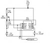
I need a schematic of how to wire a on delay timer

That after a time delay (1sec.) turns on a relay for 3 sec. then turns it off
I need to add it to a 555 circuit I've got now that turns on for 6 mins.
these times or just # I will have to adjust them as I build the project
thanks :?:
 
Suggest using an astable multivibrator built around timer IC555 for your requirement.Circuit is shown below.Here the out put level at pin 3 remains high for a long time decided by R2 and low for a short time decided by R3.With the components values shown you can vary the rate from once a second to once in 10 seconds.If necessary, you may drive a transistor with a suitable base bias resistor (say 1K) from the output.
 

Attachments

  • astable.jpg
    astable.jpg
    11.5 KB · Views: 714
Thanks Ravi I will try to build it tonite can v1 be 6-9 volts I would like to trigger it from a transistor paralled off the out put of my other 555
is a 2n2222 transistor ok to drive my relay. as Iam sure you've noticed I don't now what Iam doing
 
Relay driving transistor will depend on your relay's current requirement .The 555 is designed for high current output that can sink or source maximum of 200mA. If your relay is below this value you may directly connect it.Also the time has an ability to operate from a wide range of supply voltages.When used with appropriate supply voltage, the output is compatible with CMOS,DTL & TTL.

You must be careful when connecting an inductive load such a relay to the output of 555 or any other solid-state device. When the current through an inductive load is interrupted, the collapsing magnetic field generates a high reverse emf (transient voltage) that can damage the device. The solution to this problem is to connect a diode accross the relay coil so that it conducts and absorbs the transient.The diode must be connected so that it is reverse biased in normal operation.Hope you understand.
 
Status
Not open for further replies.

Latest threads

New Articles From Microcontroller Tips

Back
Top