Draguen
New Member
This is my first time here, so Greetings To All.
Just so you know, I am new at this, I have made a few projects before, but I learn as I go along and my only repository to electrical knowledge is the internet. I have a basic knowledge on how to use certain parts and that is about it. Anyways....
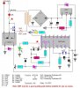
I have adapted (slightly) a 24 hour timer circuit from a certain Ron J (hope this isn't spam, but I believe I should give credit, where credit needs be), to suit my needs. The general idea was to have a "programmable" timer to cut the power to an appliance, for a specified amount of time, with the possibility to turn on and off the timer at will, and to have a reset for the timer. The circuit itself will run on 12 volts. Other than that, I do not think the rest of the info to be relevant to my problem.
When I would close SW1 (momentary pushbutton), the circuit should turn on, closing Q2, keeping the circuit on. The Relay should energize and cut the power to the appliance. The timer should also start the countdown. When the countdown reaches zero, Q1 should then cut the main power, deenergizing the circuit, and turning the appliance back on.
But what I am unsure of, is, when the timer sends Q1 high, will the circuit actually turn off? When the circuit loses power, Q1 should revert to NC state, closing the loop. Will Q2 have enough time to reverted to NO? Is there a charge large enough in the circuit to keep Q2 on when the timer sends Q1 high (thus making all this work useless)?
These questions could be irrelevant if I could make sure Q1 stays on long enough to actually kill the power and untrigger Q2?
Is this possible? If so, how (hoping that it isn't too complicated)? I have tried to research the matter, but as you can guess, no luck, maybe my noob status caused me to complicate things too much...... If there is better than what I came up with, please don't be shy.
If anyone can help, it would be appreciated.
Thanx ahead of time.
I apologize if I didn't use the right terms anywhere (if not everywhere), I unfortunately do not know better (might just be why my searches came out fruitless).
P.S. In case anybody noticed, I have yet to add the Timer's Power Off option to my schematics, I am simply gonna put a SPST switch after the diode bridge.
Edit : Might have put this in the wrong category (should'a been in Electronic Projects Design/Ideas/Reviews), If an admin reads this, feel free to move, dont think I can do it myself, and I wont double post.
**broken link removed**
Just so you know, I am new at this, I have made a few projects before, but I learn as I go along and my only repository to electrical knowledge is the internet. I have a basic knowledge on how to use certain parts and that is about it. Anyways....
I have adapted (slightly) a 24 hour timer circuit from a certain Ron J (hope this isn't spam, but I believe I should give credit, where credit needs be), to suit my needs. The general idea was to have a "programmable" timer to cut the power to an appliance, for a specified amount of time, with the possibility to turn on and off the timer at will, and to have a reset for the timer. The circuit itself will run on 12 volts. Other than that, I do not think the rest of the info to be relevant to my problem.
When I would close SW1 (momentary pushbutton), the circuit should turn on, closing Q2, keeping the circuit on. The Relay should energize and cut the power to the appliance. The timer should also start the countdown. When the countdown reaches zero, Q1 should then cut the main power, deenergizing the circuit, and turning the appliance back on.
But what I am unsure of, is, when the timer sends Q1 high, will the circuit actually turn off? When the circuit loses power, Q1 should revert to NC state, closing the loop. Will Q2 have enough time to reverted to NO? Is there a charge large enough in the circuit to keep Q2 on when the timer sends Q1 high (thus making all this work useless)?
These questions could be irrelevant if I could make sure Q1 stays on long enough to actually kill the power and untrigger Q2?
Is this possible? If so, how (hoping that it isn't too complicated)? I have tried to research the matter, but as you can guess, no luck, maybe my noob status caused me to complicate things too much...... If there is better than what I came up with, please don't be shy.
If anyone can help, it would be appreciated.
Thanx ahead of time.
I apologize if I didn't use the right terms anywhere (if not everywhere), I unfortunately do not know better (might just be why my searches came out fruitless).
P.S. In case anybody noticed, I have yet to add the Timer's Power Off option to my schematics, I am simply gonna put a SPST switch after the diode bridge.
Edit : Might have put this in the wrong category (should'a been in Electronic Projects Design/Ideas/Reviews), If an admin reads this, feel free to move, dont think I can do it myself, and I wont double post.
**broken link removed**