Continue to Site

Welcome to our site!

Electro Tech is an online community (with over 170,000 members) who enjoy talking about and building electronic circuits, projects and gadgets. To participate you need to register. Registration is free. Click here to register now.

  • Welcome to our site! Electro Tech is an online community (with over 170,000 members) who enjoy talking about and building electronic circuits, projects and gadgets. To participate you need to register. Registration is free. Click here to register now.

Tilt Switch Suggestion?

Status
Not open for further replies.

Gabe

New Member
I've got a super-simple application where I need to turn on an LED when a small project box is in a vertical position and have it turn off in a horizontal position.

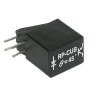
Currently, I have the LED wired to a battery via a rolling ball vibration and tilt switch that I picked up at Mouser (https://www.mouser.com/Search/Produ...010-EVvirtualkey12040000virtualkey107-2010-EV)

It's all just hand wired together since it's so simple, but my problem is that the ball switch is too sensitive and breaks the connection with even the slightest vibration. I love it because it's so compact (about the size of an axial electrolytic cap), but other than that it's not doing what I want. I'm sure what I bought isn't the proper component to be using, but without trial and error I'm having a hard time finding the right one. In my mind I want a mercury switch in the same form factor, but I don't want to use mercury in this.

I also thought I could use the same tilt switch to trigger a timer or something that turned on the LED, but that adds build complexity that I was trying to avoid. If I have to do it, that's fine, but I'm hoping I can find a different component that does what I need.

So, anyone have any thoughts on a more appropriate tilt sensor?

Thanks,
Gabe
 
Last edited:
Hello.

What you could do is make the switch activate a **broken link removed**. this will take out the breaking in the switch continuity that only last a few milliseconds, and prevent the output from switching during that time. The circuit will eventually switch after a small delay. The delay is adjustable by just changing R1 and C in the schematic.

This circuit can also be use to "debounce" buttons.


Edit: Didn't see the last bit you said about not wanting circuit complexity. Sorry about that. It's only 6 extra parts and a really easy to build circuit though.
 
Last edited:
I would make a cage for the ball, say a hollow tube that the metal ball fits within. At both ends of the tube is a pair of contacts (say made with paper clip wire) that the ball shorts out, completing the circuit and energizing the LED. Bend the tube slightly so that when the tube is horizontal, the ball becomes positioned away from the ends of the tube via gravity, where the tube dips down . When vertical, the ball shorts the contacts at one end of the tube, or the other. Of course, if you flip the tube all the away around so that the dip in the tube is at the top instead of the bottom, the ball will fall to one end of the tube, even though it is horizontal. You would want to avoid doing that, if possible. Sensitivity is based on length of tube, amount of bend, and weight of ball.
 
Last edited:
No problem...Thanks for the suggestion. I figured there was something I could do with a 555, but couldn't remember what it was called. I only dabble these days, and it's been 15 years since I did anything regularly (which was in school).

My biggest challenge with this device is space. I have about a 1"x2"x1/4" space to work with, so I'm not sure I have room to put a chip in there without resorting to SMT, which I have neither the experience nor the tools to do :) I can probably rig something up like that if I have to, though.
 
I would make a cage for the ball, say a hollow tube that the metal ball fits within. At both ends of the tube is a pair of contacts (say made with paper clip wire) that the ball shorts out, completing the circuit and energizing the LED. Bend the tube slightly so that when the tube is horizontal, the ball becomes positioned away from the ends of the tube via gravity, where the tube dips down . When vertical, the ball shorts the contacts at one end of the tube, or the other. Of course, if you flip the tube all the away around so that the dip in the tube is at the top instead of the bottom, the ball will fall to one end of the tube, even though it is horizontal. You would want to avoid doing that, if possible.

I'm 99% sure that's how the component I have works, but maybe not? I guess the two connections at one end is a little different (more like a mercury switch). The component I have has a connector on both ends, with the copper tube acting as a common connector.
 
If you make it yourself, you can adjust the sensitivity by changing the amount of bend, length of tube, and weight of the ball. Do you suspect that the ball is too light and moves away from the contacts at the end of the tube device you are using?

Maybe you can shock mount the device you have by securing it to spongy foam material, or even allowing it to float freely somewhat, using thin, coiled, flexible wire soldered to its contacts to act as "springs". Just a thought. That way external vibration is not entirely transmitted to the device.
 
Last edited:
Another idea is to do it with an LED and photo transistor.

Start with a hemisphere and make your optical path oriented vertically right down the center. Put a ball in it 1/4 to 1/3 the diameter of the sphere. The optical path will be blocked when the ball is near the bottom of the sphere. Control the angle of response by choosing the ball to sphere size ratio. Add some mineral oil if needed to dampen vibration.
 
Could you just use a capacitor to slug the switch response?
 
What size do you think I should use?
Depends what supply voltage and current-limit resistor you're using. For 3V and 100Ω then 1000uF would delay LED turn-on for ~50ms. A single 1000uF cap would probably be too bulky, but you could use several smaller caps in parallel. Or you could add a single-transistor stage and easily increase the delay 10-fold while using a smaller cap value.
 
Last edited:
i used to work on pinball machines when i was young, and many manufacturers used a nail hanging from a small wire loop that would make contact with a larger wire loop near the other end of the nail, as a tilt switch. the small loop was large enough to hang the nail through, but the nail-head was too big to fit through. the large loop was about 3 to 5 times the diameter of the nail, and was down near the point of the nail. when the pinball machine was tilted (or bumped too hard), the hanging end of the nail would make contact with the lower loop which would trip a latching relay that would kill power to the scoring mechanism until another coin was dropped to reset the machine.
 
Have you ever tried a small gyroscope chip? These are used in most applications and you can even get three 3D positions from them, but then, it may be expensive for a simple LED
 
You can try two tilt switchs in parallel at different angles. This would give you a wider rang of conntact.
 
You can also try a small magnet at one end to hold the ball in that position longer.
 
I have a few of these https://www.goldmine-elec-products.com/prodinfo.asp?number=G16881 and they are not as sensitive as the one you describe.

G16881B.jpg
 
Attach a weight to the lever of a microswitch, or even a minature pushbutton switch.
 
Last edited:
the nail with wire rings would detect tilt in any direction, microswitches and mercury switches seem like unidirectional solutions (they only work in one direction)
 
Status
Not open for further replies.

Latest threads

New Articles From Microcontroller Tips

Back
Top