Continue to Site

Welcome to our site!

Electro Tech is an online community (with over 170,000 members) who enjoy talking about and building electronic circuits, projects and gadgets. To participate you need to register. Registration is free. Click here to register now.

  • Welcome to our site! Electro Tech is an online community (with over 170,000 members) who enjoy talking about and building electronic circuits, projects and gadgets. To participate you need to register. Registration is free. Click here to register now.

Tie PIC outputs to increase current

Status
Not open for further replies.

geko

Active Member
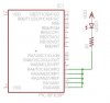
Any comments on tying several outputs of a 16F628A to increase the current to an IR LED?

Since the outputs on the PIC are MOSFETs it would seem okay to do this. I have it working on a prototype sinking 100mA through the LED and it's working as expected with the VOL around 0.6V.
 

Attachments

  • output.jpg
    output.jpg
    22.5 KB · Views: 243
IIRC, somewhere I heard it was a no-no because even on the same port, the switching time was uncertain and it could experience a transient moment where one pin is pulling high and another low.
I'm not certain whether that situation is always a problem or not, but it wouldn't really be a problem if it wasn't switching frequently anyways. It also wouldn't apply if you TRISTATED the pins to turn it off.
Did you check the spec sheet for the maximum current through Vss? And does 16F628A specify max current on a per-port basis? I've seen that on later PICs, dunno about this one.
 
Did you check the spec sheet for the maximum current through Vss? And does 16F628A specify max current on a per-port basis? I've seen that on later PICs, dunno about this one.

I did, it does, 300mA out of Vss, 200mA per port, so within spec'

I'm driving it by holding the output low and tristating the I/O.
 
Hi,

To follow on from Oznogs reply, if you see your chips datasheet, the max power though the chip is about 250ma and a max of 200ma through portA and B combined.

Your one led in that suspect configuation is taking half the max power already.

Adding one simple cheap transistor on just one pin will take all the load off the ports and protect the more expensive pic chip - any reason why not ?


Edit

Is not tying outputs together a bit like tying the outputs of two 5v regulators together, you will never get the exact voltage from them so the current draw will also be uneven.
 
Last edited:
if you see your chips datasheet, the max power though the chip is about 250ma and a max of 200ma through portA and B combined.

If you read the datasheet it is 250mA in to Vdd (sourcing) and 300ma out of Vss (sinking) The PIC only needs to sink current since the LED is connected to Vdd. If the outputs where high it would not sink or source any current.

Your one led in that suspect configuation is taking half the max power already.
Yep, only 50% of it's max spec' so no issue there. The only other connection is a 4x4 keypad matrix using the internal pullups on port B.

Adding one simple cheap transistor on just one pin will take all the load off the ports and protect the more expensive pic chip - any reason why not ?
If it works and it's a viable solution then why?


Is not tying outputs together a bit like tying the outputs of two 5v regulators together, you will never get the exact voltage from them so the current draw will also be uneven.

Not really, parallel connection of power MOSFETs is common practice to increase the output current. Since MOSFETs have a positive temperature coefficient for MOSFET Rds resistance
 
Status
Not open for further replies.

Latest threads

New Articles From Microcontroller Tips

Back
Top