Electro Tech is an online community (with over 170,000 members) who enjoy talking about and building electronic circuits, projects and gadgets. To participate you need to register. Registration is free. Click here to register now.
Welcome to our site! Electro Tech is an online community (with over 170,000 members) who enjoy talking about and building electronic circuits, projects and gadgets. To participate you need to register. Registration is free. Click here to register now.
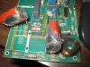
Can you post a sharper-focus picture of the board? Can't read the markings, especially on that big chunky square component (which I'm guessing is a bridge rectifier which has failed?). Any chance of a schematic?
No schematic - I rather hoped someone here might have one .
Tried another camera but not any better.
Black boxy thing has only 2 soldered connections not 4
My cameras are Auction specials for $20 and the problem is more with the flash reflection.
Loading the pics to the computer can be an issue as each camera is on a different system and some are detected some not .
Add to that this sites ridiculous size restrictions for uploading and the resizing needed to comply gives me the shits with pictures so what you have is what you get . I took about another 10 but none any better.
Now , on more important stuff which is why I posted here,its been suggested to me that the caps are 2uF 630VDC, but they must be rated for pulse application. I might be better off to get a 4uF 400VAC motor run capacitor with push on terminals, and use 2 short thick ( 1.5mm) wires to connect them to the board. That way when it next fails ( after a year or two) I can just plug in a new 4uF capacitor.
So all is not lost yet by silly side issues trying to provoke a response
You cant guess at design specs, but from my experience, I would find the exact colour and part in the same or better 350vac rating with the biggest value in plastic film.
What you have found is probably ok. This is some pics of an electric fence battery powered. The capacitor used is a 2.2uF 250v_MKT. I use an old Nikon camera 4Mpixel, which was cheep cost me $5 in a garage sale, For this type of photos I use Macro & daylite shady area. If you use flash there is too mutch reflection. Using a 4mpix camera the pictures don't need to be re sized to post.
Can you post a sharper-focus picture of the board? Can't read the markings, especially on that big chunky square component (which I'm guessing is a bridge rectifier which has failed?). Any chance of a schematic?
Eh? Even my grandkids' cheap cameras can do better than that .
Hey I have cataracts on both eyes and got one fixed yesterday . Looking at the photo its actually quite clear and sharp now . Had your eyes checked lately?
Its simply stunning how the eyesight detail and contrasts go as cataracts develop , you don't notice them creeping up but boy do you notice it when they are fixed.
ESR = Effective Series Resistance, the critical parameter, thats causes self heating, if ignored causes the cap to blow up like yours.
MKT=metallized plastic high K with terminals can be PE or PU
PU = PolyUrethane a better self healing lower ESR, lower leakage cap
PE=PolyEthylene and lower cost low ESR cap
self healing , if hotspot fuses a strip of metal conductors in a short, the capacitance reduces, the metal fuses open, the plastic cools and heals. Like having many small caps in parallel and one defective cap fuses open and the bulk surbives
If you had read my datasheet it would have explained most of this. Sorry. This takes a longtime.
This site uses cookies to help personalise content, tailor your experience and to keep you logged in if you register.
By continuing to use this site, you are consenting to our use of cookies.


") .
.