Okay so I posted the problems I'd been having with my motor controller in a thread a few months ago (https://www.electro-tech-online.com/threads/mysterious-current-flow.103091/) but was still unable to get the controller to work reliably. I put the project on hold because I didn't have the time to fiddle with it, and am now returning to get my revenge")
I've decided to scrap the old controllers and start again, so basically what I'm asking is whether my new proposed motor controller has anything wrong with it. I'm studying mechatronics engineering but we have not done any theory related to motor controllers yet, so please correct me if I'm doing anything wrong! (In particular, is the cap on pin 5 of the mosfet driver (1uF) too big?)
Some background info:
The datasheets:
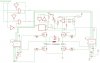
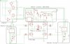
I have attached the schematic for the motor controller - the one image is just of the schematic, the other is divided into different sections, eg. current limiting, mosfet driver, etc.
Thanks for the help/comments! It is much appreciated
I've decided to scrap the old controllers and start again, so basically what I'm asking is whether my new proposed motor controller has anything wrong with it. I'm studying mechatronics engineering but we have not done any theory related to motor controllers yet, so please correct me if I'm doing anything wrong! (In particular, is the cap on pin 5 of the mosfet driver (1uF) too big?)
Some background info:
- I'm making a Segway, but am having problems with the motor controller (these can be viewed in the thread I posted at the top^)
- I am using two wheelchair motors, controlled by two seperate motor controllers
- Because it's a Segway, the motors will be changing direction often
- The motors draw about 10 to 15amps stalled
- I have added 0.7 ohms resistance in series with the H-bridge so that if there is a short circuit, the max current that can flow is about 50A - which is below the current rating of the mosfets so they won't blow before the current limiting kicks in / fuse breaks
The datasheets:
- Mosfets STP55NF06 http://www.st.com/stonline/books/pdf/docs/7544.pdf
- Mosfet driver IR2113 http://www.irf.com/product-info/datasheets/data/ir2110.pdf
I have attached the schematic for the motor controller - the one image is just of the schematic, the other is divided into different sections, eg. current limiting, mosfet driver, etc.
Thanks for the help/comments! It is much appreciated