Continue to Site

Welcome to our site!

Electro Tech is an online community (with over 170,000 members) who enjoy talking about and building electronic circuits, projects and gadgets. To participate you need to register. Registration is free. Click here to register now.

  • Welcome to our site! Electro Tech is an online community (with over 170,000 members) who enjoy talking about and building electronic circuits, projects and gadgets. To participate you need to register. Registration is free. Click here to register now.

This is a Circiut I designed for a door Alarm - help improve it please

Status
Not open for further replies.

OsMaN_93

New Member
Hi,

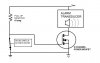
So you may have seen my previous posts, I have a school project where I have to make a door alarm this is my idea:

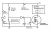
Its a basic door alarm, it is ment to have a magnet, when the door is open the circiut is complete;
The pic chip, has most of the processes on it...
**broken link removed**

Can you, please, suggest some improvemnts i can make to this, I don't think its perfect :s
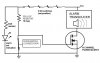
 
Last edited:
It would be better to have the door open event cause an open circuit rather than a closed circuit, for several reasons. First, because switch failure is much more likely going from open to closed than from closed to open...Or, a better way of seeing this is that if the switch were to fail with the door closed, you will automatically know why and be able to correct it, OTOH a switch that closes upon the opening of the door may be unreliable over many make-break cycles that stress the switch mechanically. Also, if the alarm you are designing has mains voltage contact pitting might eventually occur.

The same would hold true for a magnetically closed switch, but the fault condition would make itself known with a false alarm when the door is closed, so corrective measures will be obvious.

Also, a would-be entrant to the door could easily disarm your open-door-to-make circuit by simply cutting the wires, OTOH a switch that is magnetically closed by the door magnet can't be so easily disarmed because a cut wire will trigger the alarm.

The only complication to this type of circuit is that the alarm transducer has to be indirectly triggered by the opening of the switch where direct triggering is possible with the more simple open-door-to-make type circuit you described. With an open to break type door switch a pull-up or pull-down resitor can be used to gate an FET (depending on the potential at the other end of your switch circuit) that can in turn be used to energize your alarm transducer.
 
My security system in my house utilizes NC (normally closed) switches for the doors and windows. Inside them is a little metal ball that completes the circuit when a magnet is on top if it. With NC, if a door is opened, you will know, and if someone cuts the wire at either end you will know as well. It also combines a resistor at one end of the switch with another across the two terminals of the switch in the circuit box so that if a thief connects the two terminals together to avoid detection the security system will notice the difference in voltage and still see that it's being tampered with. I believe this is referred to in the security community as 'double eol resistors'.
**broken link removed**

EDIT:Ha i just looked at the top of the page and saw an ad for ADT security monitoring... Good ad scripting there! (BTW those ADT guys are crooks!)...
 
Last edited:
Hi,

Thank you so much for your replies, I think they will help me a lot. But please remember, its a school project, and I'm 16 (therefore very little experience.) :s

Do I need it to be this complicated? :)
 
Last edited:
Here is a very simple circuit that will accomplish what you want with a small number of components and with a closed switch when the door is closed.

It isn't precisely how commercially produced alarms work, but it is a good, simple, effective circuit. It might be made better with a P-channel but you get the idea.

And please, don't shortchange yourself because you are young. If you need an explanation please ask.
 

Attachments

  • ALARM.jpg
    ALARM.jpg
    31.2 KB · Views: 438
Ah, I drew that little schematic and afterward thought of a small, simple improvement.

If you are interested in this circuit and want a simple way to add an "alarm set" feature, you could try an "electronic combination lock", which is simply an AND gate with switches. The Vcc line would be interrupted with several normally open pushbutton switches. However many you wish, it isn't important...but the more the "better". Lets say you hardwired 5 switched in series between Vcc and the pull-up resistor. You would mount the 5 switches randomly on the front panel of an enclosure. Then, you would add several more "dummy" switches that aren't electrically connected, just mounted on the front panel and serving no purpose. You, the designer, only know the combination of 5 switches that electrically connect the power supply to the circuit. When all 5 are closed, the alarm is set. It might even be a good idea to put a single LED and current limiting resistor in parallel with the pull-up resistor to ground to indicate the alarm is energized. I'm going to edit my schematic to illustrate this.
 
EDIT:Ha i just looked at the top of the page and saw an ad for ADT security monitoring... Good ad scripting there! (BTW those ADT guys are crooks!)...

Firefox Ad Blocker FTW.
 
OK, here is the schematic with the "combination lock" switches. Remember, there are 5 of them indicated, per this example, that are electrically connected. Any number more would be added to the panel as decoys or dummies.


Edit...One more additional idea for your circuit. This simple alarm doesn't need to be limited to one alarm switch. You could just as easily add several contact points (other doors, windows, etc) throughout the building being secured. In this case, instead of one switch pulling the gate of the MOSFET to ground, you would have several switches all wired in series (and closed when the door/window is closed) in place of the single switch in the present schematic. This would be an OR gate configuration. Any one of the series switches, when open, will trigger the MOSFET gate and energize the alarm transducer. (This switch "OR" that switch).

BTW, I am very glad to be helping a High School age kid. We get a lot of engineering students at the college level here who put less thought into their projects than you already have. I hope I can be an encouragement for you to make an A on the project and also take it seriously and learn, if you feel you have the aptitude.
 

Attachments

  • ALARM.jpg
    ALARM.jpg
    41.6 KB · Views: 322
Last edited:
ke5frf, may I ask why you're suggesting going with switches in series as appose to a simple digital combo lock? Just built one in my ECE class using AND, OR, J-K flip flops and a 555 timer. Wicked stuff.
 
ke5frf, may I ask why you're suggesting going with switches in series as appose to a simple digital combo lock? Just built one in my ECE class using AND, OR, J-K flip flops and a 555 timer. Wicked stuff.

Well, because he is in High School, not 4th Year college engineering, and looking for a simple solution. I was simply trying to offer the most basic concept that I could come up with with the simplest wiring layout and yet effective. A combination lock with a good number of dummy switches would be pretty effective without involving an entire circuit unto itself.

>>>>Duh, I need to rethink the combination lock now that you mention it. All it takes is one switch to open the circuit.
Hmmmm. I feel like a dummy, too hasty in my submission of the idea. Too eager for simple.
 
Last edited:
Good point. Had to reread the whole thread to see that post. Guess I proved that reading is lost on some. **broken link removed**
Sorry about that.
 
OK, still keeping it simple, yet not SOOO easy to break. Instead of 5 switches in series, how about three parallel rows of two switches each. This way, the entrant has to know at least three of the switches to press to get an open combination. Really, it should have been a parallel combination to begin with. Now that I think about it, two switches aren't necessary for each row,they are only a hindrance for the alarm setter really. And as simple as it is, it does have a couple of obvious flaws.

One, All it takes with the switches in parallel to REALLY set the alarm is one series pair of closed switches. The alarm setter could get lazy and neglect to set the others.

Two, the unauthorized entrant only has to press each switch once to disarm the alarm, as long as he doesn't punch switches randomly he will get it. Now, I would think most people wouldn't realize this when they walk up to, what appears to be, a keypad. I think we have all become sort of acclimated to passcodes that it would be instinctual to hit random keys rather than each switch one at a time. Maybe in being simple and archaic it does the trick :)

Also, another disadvantage is that if someone came up and randomly hit switches and failed to disarm it, the "owner" of the alarm would have a heck of a time getting it disarmed. perhaps a secret master switch would be a good idea.

Also, probably better than ANY of these simple, silly combination switches would be a real KEY SWITCH. Do away with all the combination lock switches completely. Get a lock and key switch where when the tumblers are lined up the circuit completes. The owner of the alarm would be the only one with the key. This is how alarms were set before digital panels anyway.
 

Attachments

  • ALARM.jpg
    ALARM.jpg
    41.9 KB · Views: 288
I don't know if the OP will return, but I've been having some fun with the little circuit, tossing some other ideas and suggestions around in my mind.

As was mentioned by the other poster, you could very well incorporate a more sophisticated logic-based combination keypad, or even a microcontroller based keypad with programmable passcodes. This would be fairly involved though. I'm not sure how much time or resources you wish to devote.

A simple modification you could make here could be a "panic button". This might be accomplished by wiring up a switch in parallel with the source-drain of the MOSFET. If you don't understand those terms I can explain if you wish. At any rate, pressing the switch would bypass the MOSFET and turn the alarm transducer ON until the switch is opened.

Another modification might be an alarm set-delay. This could be accomplished with a 555 timer based circuit. Basically, the key-switch would be replaced with a relay, the relay would be turned on by a transistor, the transistor would be switched by the output of the timer, and the timer would be triggered by the key-switch. This would permit setting the alarm and giving yourself X amount of time to vacate before the alarm is set.

Of course, the problem here is that if the alarm panel is located within the secure zone, opening the door will trigger the alarm before you have time to deactivate. The simpler circuit concept would have the panel placed outside the secure perimeter.

To overcome this problem, you could have a 555 based delay circuit built into the alarm trigger (the MOSFET gate)

I've posted this in threads before, but modular relay timers are easily obtained to perform these delay functions. Some are fairly cheap. I was just thinking that the MOSFET could be used to switch a modular timer instead of directly switching the alarm transducer, and in turn the modular timer could energize the transducer after a set amount of time.

In that case, the key-switch or the key-switch/timer/relay should be moved so that the entire circuit is powered by setting the alarm instead of just the gate circuit. The reason being that resetting the timer at the transducer would probably require a power reset.

Just some concepts that might be implimented. I've thought about building my own alarm panel in the past. I'm not a big fan of paying an alarm company a monthly fee to install and monitor an alarm. Its a ripoff. I could easily build my own security system, simple like this. Most thieves are deterred by having signs anyway, and having a siren go off is just an added benefit to scare off a bold thief. I could imagine the look on his face seeing a homemade alarm panel!


...I just realized another flaw that I'll correct. One problem with this circuit as it stands is that the MOSFET driver doesn't latch the alarm. Upon closing the door it will silence. I need to incorporate a gate latching technique.
 
Last edited:
Another "final draft" :eek: with a latch and reset method for the MOSFET.

A diode, capacitor, and switch are added to hold the gate signal high even when the door switch is closed. The gate can be reset by discharging the capacitor through the momentary key switch.

So, to disarm the alarm, two keys would be neccessary, but I'm sure a matched set of tumblers could be purchased so that one key could be used to reset both switches.

Even though this isn't my project, I would appreciate a critique of the circuit for any mistakes I've made. I'm not 100% certain everything is correctly thought out.
 

Attachments

  • ALARM.JPG
    ALARM.JPG
    45 KB · Views: 279
Last edited:
I must say WOW! Thanks for all the posts!

I read them all, which was quite challenging! and now I'm full of questions.. haha, it was difficult understanding some of it, but it does make sense.

1. can you please explain "MOSFET" i have never heard of it :/
2. why do you draw your resistors in a zic-zac line :s

Thanks


Great, I'm glad you are interested in learning. I wish I had been as interested at your age, it took me too long to mature :)

OK, 1) a MOSFET.

I will give you a brief explanation, but I challenge you to use a search engine with MOSFET as the keyword and read as much as you can. You'll find technical as well as layperson discussions and will glean a lot.

A MOSFET is a type of FIELD EFFECT TRANSISTOR. (Metal Oxide) Just like the LEDs and PIC in your original circuit, it is a solid state electronic device, or semiconductor. In short, it has three terminals called the "GATE", "DRAIN", and "SOURCE". In the diagram of the N-channel Mosfet in my schematic, the Gate is to the left, connected to the switch. The Drain is connected to Vcc and the transducer (alarm sounder), and the Source is connected to ground potential.

There are two types of MOSFETS, P and N channel. The N-channel is characterized by switching ON when a proper positive voltage is applied to the gate with respect to the ground reference at the source terminal. In a power MOSFET this might be 12 volts. So, when Vcc is applied to the GATE through the "pull-up" resistor, the gate collects an electrostatic charge at the same Vcc potential. The gate is insulated from the Drain and Source, but the electric field produced by the charge influences the conductive state of the Drain and Source. In the case of N-channel, the D-S junction will conduct with almost zero resistance, not unlike a closed switch. This is only possible when the door switch is OPEN.

This is because a closed door switch brings the gate to GROUND POTENTIAL, meaning zero volts. You may think, why? The Vcc is still connected. Yes, but through a 10 megOhm resistor, which "drops" the voltage across it to the potential that ground provides. When there is no ground potential (switch is open), there is no where for the Vcc to go, therefore Vcc is presented to the gate terminal and the MOSFET switch conducts and energizes the alarm sounder.

A P-channel MOSFET works quite the opposite but still based on the same principals. A ground potential will turn the MOSFET switch ON and Vcc will turn it OFF. Other than that, the concept is the same. N-channels are schematically identified by the arrow pointing toward the gate, whereas P-channel points away from the gate. That is, in most standard schematics.

There is lots more to say here, and I will go into why the "reset" switch, capacitor, and diode are needed later. But I suggest you read further on the basics of MOS technology.

2)
The resistor? That is technically the standard symbol for a resistor, though sometimes a rectangular shape is used. As you browse the internet for MOSFET information you'll see it illustrated both ways.
 
Last edited:
Status
Not open for further replies.

Latest threads

New Articles From Microcontroller Tips

Back
Top