Continue to Site

Welcome to our site!

Electro Tech is an online community (with over 170,000 members) who enjoy talking about and building electronic circuits, projects and gadgets. To participate you need to register. Registration is free. Click here to register now.

  • Welcome to our site! Electro Tech is an online community (with over 170,000 members) who enjoy talking about and building electronic circuits, projects and gadgets. To participate you need to register. Registration is free. Click here to register now.

The Novice and the SMPS

Status
Not open for further replies.

Musicmanager

Well-Known Member
Hi Guys

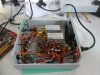
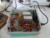
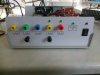
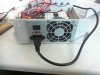
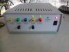
Some of you may know, I've been laid up at home for a while recently and to avoid complete boredom I've been sorting through some junk and having a clear out. Also a while ago, I bought a 0 - 30vdc power supply kit from Banggood but I've only managed to partly build the project as yet. In the sorting process I came across a PSU for a computer, actually a SMPS, brand new in a box and decided it would be useful to convert it for a spare bench power supply because it offers 12, 5 and 3.3 vdc and with decent power, as well as -12 & -5vdc.

The basic conversion was relatively easy, but I did find a challenge in loading the unit without using the customary beefed up resistor trick. I used an LED on each of the positive outputs which is sufficient to keep the unit on and provides some pretty lights for those dark evenings by the solder station. The final challenge involved an indicator to tell me when the switch mode was active/inactive. There is a circuit in the box which provides this info for a computer but it is only signal so insufficient to power and LED. I used my new found novice learning, taught by you guys and put the signal wire to the base of a BC548; voltage and resistor to the LED anode; Gnd to the Emitter and Collector to the LED cathode.. .. .. I was a little surprised that it worked !

There are some pics below for you to have a good laugh at ..

Thanks guys

S
 

Attachments

  • ATX SMPS 1.JPG
    ATX SMPS 1.JPG
    1 MB · Views: 292
  • ATX SMPS 2.JPG
    ATX SMPS 2.JPG
    1 MB · Views: 327
  • ATX SMPS 3.JPG
    ATX SMPS 3.JPG
    687.6 KB · Views: 229
  • ATX SMPS 4.JPG
    ATX SMPS 4.JPG
    848.5 KB · Views: 203
  • ATX SMPS 5.JPG
    ATX SMPS 5.JPG
    617.4 KB · Views: 214
Hi Alec

No, no resistor .. .. the spec I found suggests current on this line is limited to 10mA so I didn't think it necessary. However, if I need to add resistor I'd need to think about how to size it correctly. Thank you, I will check again.

S
 
Probably overdriving the LED. Does it feel warm in the negative lead?

Normally BC546 only saturates output switch low, when input current is at least 5% of output current and does not need more than 10%.
So if on same 5V supply it might be 20x input current or more. 3V drop from 5V @20mA is 3V/0.02A= 150 ohms from collector or 5V in series.

1.5k for base. If not handy value use 220 Ohm and 2.2k

I tend to use AWG 30 magnet wire for up to 1A , and glob Polyurethane caulking on any big parts so it will still work after long transit on rough truck or a drop test from the bench ;)

Good work Mm
 
Hi Tony

Thanks for that information, clearly I should have looked into the transistor spec much more than I did. To be honest, it is a component I had left from some timers I built to a kit design, I did think to check the current from the signal line but not the effect on the transistor. The calculation method is useful to keep noted also. I'll get it sorted in the morning.

The wire in the box is without exception the wire used with the original nylon connectors for motherboard etc; all I've really done is to put the unit into a more practical enclosure and add some banana terminals and pretty lights. I'm very much a novice enjoying a new hobby with the help of you guys and the 'buzz' of surprise I get when I power up for the first time and it works is priceless ( I must admit, I did plug this into an extension lead in the garden, and switch on from the house for the initial trial :) ) I can quite readily see that there will be some issues around things working loose in time but once I'm certain of the operation I can deal with those quite easily.

Thanks again

S
 
Polyurethane like PL 200 has good adhesion, stiffness and dampening qualities. Commercial grades are used in PC PSU's.

I once fixed our secretary's $3k Mac monitor once because the (unnoticeable ) flyback transformer vibration caused micro cracks in a solder joint visible with a 10x lens. Even Apple makes misteaks ;)
 
That sounds like a transition problem from leaded to unleaded solders. Loss of ductility and fatigue resistance.
 
Nice and neat mr manager.
I have a stash of pc supplies, I have made one into a bench supply but its not as neat.
The power good line on mine powers a led no problem.
I also have made one adjustable, but its not easy, later chips have under/over voltage protection, you have to fool this before you mess with the feedback to adjust the voltage.
If you manage to find a real old one that has a tl494 you can easily make a adjustable voltage and current supply.
 
UP is usually on, although not many things have toggle switches anymore. Turn the power switch around 180 degrees.
I remember when someone had built a bunch of stuff with the switches upside down.

Light switches in the home are UP is on.
 
Hi Ian

Got over the embarrassment then :)


When the switch is on the LED is above the switch, next to the OFF position..

Ah, no not so.. .. the unit has a mains power switch on the rear, but the switch on the front operates the switch mode only. The LED above the switch illuminates to indicate mains power in the circuit, that is the switch on the back is on.

Clear as mud Eh ?

S
 
It looks like we both have been leading a sheltered life. We are both right: See https://ux.stackexchange.com/questions/36207/which-way-should-be-on-for-a-switch

Thanks for bring this to my attention. It's a Country-specific thing.

Having dealt with non-English speaking people, I now know what a "plug point" is. In the US, we call them electrical outlets. It also wasn't a common word I learned in German either. German and English is kinda close if it wasn't for all of those pronouns without any rhyme or reason for masculine, feminine or neuter.

I digress.

I wish that the curriculum would have been focused on scientific or traveling. e.g words for Taxi, bus, rest area and bathroom were never discussed. The boot (what we call the trunk) of a car was discussed. For Brittish, s, z's and c's get messed up. I know I use grey and gray interchangeably.

100 VAC (Japan) and 277 (US lighting in some 3 phase buildings ) threw me for a while too. We had some Japanease equipment that operated off of 100V. Fraunhoffer (a German outfit) shared some space in our building when they were doing research on Aluminum foam. Since they were using furnaces from Germany, they got a German distribution system which, I think was mainly 240. We were 120/208/277 single phase, 208 three phase and 460 three-phase.
We moved from a 240 V environment. Most of the stuff worked with tap changes except the diffusion pumps (1100 W). The heaters were eventually changed to 208V. The 460 was used for the HVAC system which was about 36 air to water heat pumps.
 
Huh, tell me about it !

My son runs a commercial laundry business that used to be my wife's enterprise in younger times. There is a bank of large commercial tumble dryers on one wall and on top of them is a large box of cartridge fuses. Why ? Because they were built in Canada and the circuits are black live and red neutral and I forget regularly and blow the ***** fuse again !!!!

S
 
Canada is 120 V and therefore probably split-phase like the US and RED would be the other phase.
e.g for the US: black, white, green and red. Green with a yellow stripe is also used along with green in some very special installs.

You, on the other hand should probably "tape" the wire colors the correct color for your locale. It's permissible, for us to say run all black wires for the current carrying conductors and tape the ends the appropriate wire color. I'm not sure of the full restrictions.
 
That sounds like a transition problem from leaded to unleaded solders. Loss of ductility and fatigue resistance.

... could be if it were post y2k but this was made circa '95

.. 2 years ago found tin-lead soldered Omron relay on Stove top board with same failure mode on not too old a stove. but also pre-RoHS
 
Status
Not open for further replies.

New Articles From Microcontroller Tips

Back
Top