Heidi
Member
Dear friends,
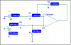
Here's the difference amplifier I'm looking at, assuming the op amp to be ideal:

Its input resistance is defined as the resistance seen by Vi, as shown below, that is Ri=R1+R1.

For the right circuit below, knowing the input resistance as 2kΩ, I can tell that before the op-amp output voltage saturates, the ratio of the input voltage and the input current is equal to 2KΩ. But when I look back to its original circuit on the left, what can it tell us knowing the circuit's input resistance is 2kΩ? If the circuit's input voltage is V1-V2=3-1=2 Volts, what is defined as its input current? What is the purpose of defining the input resistance like that anyway? Thank you!

Here's the difference amplifier I'm looking at, assuming the op amp to be ideal:
Its input resistance is defined as the resistance seen by Vi, as shown below, that is Ri=R1+R1.
For the right circuit below, knowing the input resistance as 2kΩ, I can tell that before the op-amp output voltage saturates, the ratio of the input voltage and the input current is equal to 2KΩ. But when I look back to its original circuit on the left, what can it tell us knowing the circuit's input resistance is 2kΩ? If the circuit's input voltage is V1-V2=3-1=2 Volts, what is defined as its input current? What is the purpose of defining the input resistance like that anyway? Thank you!
Attachments

Last edited:

