Ricardoco
New Member
ok ive done a good bit of my programming from examples found on this site and else where
but i cant find examples for a few things i need so rather than asking several questions
ive designed a circuit and the program that runs it will answer all my questions at once.
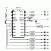
I would like the 6 led's on PORTB to light sequentialy depending on the position of the
potentiometer
I would also like led 1a to be on for 1 second and off for 1 second when Led 1 is on,
and the time led 1a is on to be increased to 10 seconds when all the PORTB led's are on
being off for ten seconds as well. a sort of a pulse that increases with the potentiometer.
any help or links to examples that will help me achieve this would be magic.
INPUT TO PORTB.6 = Potentiometer
OUTPUT FROM PORTA.0 = led 1a
OUTPUT FROM PORTA.1 = led 2a
OUTPUT FROM PORTB.0 = led 1
OUTPUT FROM PORTB.1 = led 2
OUTPUT FROM PORTB.2 = led 3
OUTPUT FROM PORTB.3 = led 4
OUTPUT FROM PORTB.4 = led 5
OUTPUT FROM PORTB.5 = led 6
i have included a cuircuit diagram that should do the trick but im new so any input will not go un noted thankyou
but i cant find examples for a few things i need so rather than asking several questions
ive designed a circuit and the program that runs it will answer all my questions at once.
I would like the 6 led's on PORTB to light sequentialy depending on the position of the
potentiometer
I would also like led 1a to be on for 1 second and off for 1 second when Led 1 is on,
and the time led 1a is on to be increased to 10 seconds when all the PORTB led's are on
being off for ten seconds as well. a sort of a pulse that increases with the potentiometer.
any help or links to examples that will help me achieve this would be magic.
INPUT TO PORTB.6 = Potentiometer
OUTPUT FROM PORTA.0 = led 1a
OUTPUT FROM PORTA.1 = led 2a
OUTPUT FROM PORTB.0 = led 1
OUTPUT FROM PORTB.1 = led 2
OUTPUT FROM PORTB.2 = led 3
OUTPUT FROM PORTB.3 = led 4
OUTPUT FROM PORTB.4 = led 5
OUTPUT FROM PORTB.5 = led 6
i have included a cuircuit diagram that should do the trick but im new so any input will not go un noted thankyou
")
