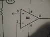
Building my first project. I'm a total novice. After reading several books, I seem to be getting a handle on reading schematics. Only one symbol has me confused at this point. It's simply an arrow coming off the IC. Some guides indicate this is a male connector but no clue how to connect it? Another book suggests this could be a short-hand for connecting to + rail? Any help would be most appreciated.
Continue to Site