Continue to Site

Welcome to our site!

Electro Tech is an online community (with over 170,000 members) who enjoy talking about and building electronic circuits, projects and gadgets. To participate you need to register. Registration is free. Click here to register now.

  • Welcome to our site! Electro Tech is an online community (with over 170,000 members) who enjoy talking about and building electronic circuits, projects and gadgets. To participate you need to register. Registration is free. Click here to register now.

testing a voltage regulator

Status
Not open for further replies.

tab a

New Member
This is in regards to the L78MR05 but the theory I'm interested in, I'm guessing would apply to others.

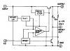
What's the purpose of the 'delay' cap on pin 2?

Pins 4 and 5 are 5V outputs. If the input voltage and the ground are correct, will the outputs be correct IRRESPECTIVE of any problems in the circuits downstream from 4 and 5 (barring 4 or 5 being shorted to ground?)? In other words, if voltages at 4 and 5 are wrong, is it highly likely the regulator is bad?

Sorry if this seems really basic, but it's where I am on the learning curve!

Thanks.
 
I've heard of this chip from your post, but I have a datasheet on my pc. Pin 5 is the output (regulated voltage, referred to ground). Pin 3 is an auxiliary output that generates a reset pulse for micro controllers.
Most modern micro controllers have built-in circuitry for the power-up reset. The should be no problem using this chip as an usual 3-terminal regulator for most applications? What do you connect to the output?
You must measure the voltage between pin 5 and ground.
 
Last edited:
I think you mean pin 4 is aux reset?

I don't want to use it as a 3 terminal--it's already in a circuit, using all 5 terminals.

Just trying to find out if my PRESUMPTIONS about my test results, and the theory behind them, make sense. :)

Thanks.
 
tab a said:
I think you mean pin 4 is aux reset?
Of course, you're right. Pin 3 is ground :)

I post the block diagram for anybody whot may read this thread.


EDIT: do you have the datasheet? they show some useful waveforms and data for understanding the operation of the IC.
 

Attachments

  • 05.png
    05.png
    9.4 KB · Views: 161
Last edited:
Status
Not open for further replies.

Latest threads

New Articles From Microcontroller Tips

Back
Top