Continue to Site

Welcome to our site!

Electro Tech is an online community (with over 170,000 members) who enjoy talking about and building electronic circuits, projects and gadgets. To participate you need to register. Registration is free. Click here to register now.

  • Welcome to our site! Electro Tech is an online community (with over 170,000 members) who enjoy talking about and building electronic circuits, projects and gadgets. To participate you need to register. Registration is free. Click here to register now.

Test Light For Automotive Installs

Status
Not open for further replies.

What

New Member
Hello Everyone, once again I need your expert knowledge.
I install car audio, and remote starters, and the like. I would like to make a test light the I can hook up to power and ground with some aligator clips, and then probe wires. If it is postive it will turn a red LED on. Or if its GND then it will turn on the Green LED. So far it works, The problem is the LED's both light up once powerd up.

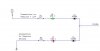
I have a schematic below. I cant figure out how to isolate both led's from the supply circuit, without isolating one from the Probe circuit. Hopefully you understand what im trying to say.

Or maybe im just going about this the wrong way all together. Prehaps I should use transistors to switch them on and off. only I dont really know how to wire them up. Please Help me out.
 

Attachments

  • Test Light.JPG
    Test Light.JPG
    15.3 KB · Views: 163
You have shown the isolating diodes the wrong way around, but as the LEDs both light up when you apply power, this must just be a drawing error.

You don't really have a problem because when you use the probe, one LED will go off leaving the correct one illuminated and brighter. Just look on the fact that they are both otherwise on as an indication that the circuit is connected up correctly - like a dual power-on indicator.
I can't believe you would be worried about draing the car battery!
 
hi what,
Attachment, have look.

Use 1.3W Zeners.

Lets know

EricG
 
Last edited:
I am not worried about draining the car battery. I just dont want any LED on until I probe a wire. I am already going to use a yellow LED to indicate power. I mean if I wanted them both on, couldnt I have not just left out the diodes? as the LED themselves will go off leaving the correct one illuminated and brighter when probing.

Now I think I have 1w zenor's will those work? Is that really going to solve my issue? So far I have been unable too using my zenor diodes.
 
hi what,

I have 1w zenor's will those work?
If your zener diodes are 6V8 at 1 Watt, this would suggest that as W=V * I
and transposing I=W/V,,, I= 1/6.8 = 147mAmp.
[Calc your R1 to give the LED the max brightness, without exceeding its rating]

Is that really going to solve my issue?
If I didn't think so, I wouldn't have posted it!
It would take you all of 10 minutes bench time to give it a try.

So far I have been unable too using my zenor diodes.
What zeners and how were they connected?

EricG
 
Last edited:
The Zeners diodes I tried using were 1n4741

And they were connected as to your diagram you posted; except Without that fancy math calculation u just posted for the resistor value
 
Last edited:
What said:
The Zeners diodes I tried using were 1n4741

And they were connected as to your diagram you posted; except Without that fancy math calculation u just posted for the resistor value
!N4741 is an 11 volt zener. It won't work. You need a 6.8V zener, as Eric says. If you want to stick to the same series, use 1N4736.
 
You don't really need zener diodes. See attached circuit. You can add a resistor (say 1K) in parallel with the LEDs if you want it to be less sensitive to leakage currents.
 

Attachments

  • simple-test-light.GIF
    simple-test-light.GIF
    8.7 KB · Views: 158
Status
Not open for further replies.

Latest threads

New Articles From Microcontroller Tips

Back
Top