Continue to Site

Welcome to our site!

Electro Tech is an online community (with over 170,000 members) who enjoy talking about and building electronic circuits, projects and gadgets. To participate you need to register. Registration is free. Click here to register now.

  • Welcome to our site! Electro Tech is an online community (with over 170,000 members) who enjoy talking about and building electronic circuits, projects and gadgets. To participate you need to register. Registration is free. Click here to register now.

Terminator poster project - help/advice

Status
Not open for further replies.

Peter_wadley

New Member
Hi there,

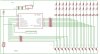
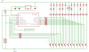
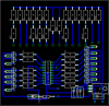
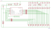
I've finished the schematic of my current project.

This is the first time Ive ever really drawn my circuits out on paper.. I used eagle AutoCad..

Does it look the way it should?

I m using the internal 4mhz clock.

Once problem.. the 5v regulator is getting rather hot.. even with a large heat sink..

Im guessing this is because it is going from 24volts to 5volts..

Could I use a voltage divider to distribute the heat over a couple resistors?

Could anyone tell me how to do that?

Again im really new to drafting schematics .. any advice or pointing out of flaws would be really helpful


Thanks
 

Attachments

  • Schematic.JPG
    Schematic.JPG
    142.2 KB · Views: 216
  • P7180046.JPG
    P7180046.JPG
    554.6 KB · Views: 191
  • P7180047.JPG
    P7180047.JPG
    635.3 KB · Views: 175
  • P7180048.JPG
    P7180048.JPG
    526.4 KB · Views: 175
I m using the internal 4mhz clock.
You can try a slower clock speed by changing the OSCF bit in the PCON register to save power.
Could I use a voltage divider to distribute the heat over a couple resistors?
You could put a resistor in series with the input to the regulator. You'd also need a cap (0.1uF) across pins 2 & 1 of the regulator. You'd need to measure the maximum current drawn by the regulator (Probably when the max number of the transistors are being turned on by the PIC) and then use ohms law to calculate a resistor value that would give you around 10V at the input of the regulator at the minimum input voltage on the 24V line. If the transistors were all FETs, current draw wouldn't be an issue. Changing them to darlington's would also work. You may be able to also just get away with less base current and use higher value base resistors. Depends on the beta of the transistors and the LED current.
 
I spy 13 leds.

If each LED takes 20ma then thats 260ma

A 7805 with a 24v input and 5v output has to drop 19v at 260ma.

Thats a good 5 watts of dissipation
 
Boncuk said:
Actually theyr'e just 12 LEDs. One is not connected to R29.

Boncuk


Good eye Good eye

but actually your both mistaken :D

Each LED represents either 4 or 11 LEDs.. since I only need once place to connect them on the PCB.. in actuallity they are on the Poster.

Sorry pic but i think you are also mistaken regarding the current.

The LEDs are being driven by the 24v rail

the 7805 is actually in parallel with the LEDs.. yes it is dropping 19volts and from using my multimeter I have found that the current of the microcontroller - will all the transistors are active.. is 60 ma .. which is 1.15 watts

is there a proper way to reduce the power dissipiation of the regulator?

I will fix the unconnected resistor - thanks!
 
Hi Peter,

come on, Eagle schematics can look better, e.g. having VCC and GND symbols too, and labels at the input and output connections of the PIC. You'll find it very useful when you route the traces on the PCB.

A german saying: "A good horse never jumps higher than it has to", meaning why do you put in 24V just to supply one lousy LED from each output?

Putting in 9V you still have enough to play with.

A fixed voltage regulator tends to oscillate and consequently gets hot. Therefore a decoupling capacitor of 100nF on both, input and output pins connected directly to the ground pin is an absolute 'MUST'.

Using a heatsink like the SK104 you'll never get a hot voltage regulator provided you decouple it properly.

Also use a small electrolytic capcacitor (47 to 100uF) at the regulator output. The PIC will appreciate that very much.

Kind regards

Hans
 
Last edited:
Hi Peter,

here is just one example. If you want more, I'll send the original eagle.sch files via email.

I'm using Eagle version 3.55 although I also have Eagle 4.16. It is only slightly better than the older version. The autorouter surrounds itself as usual.

Making PCBs I import the board files into the new version, because labels are better readable (another type of characters)

Hopefully that file is "readable" at all.

Regards

Hans
 
Last edited:
Peter,
You saved your schematic as a fuzzy JPG file type instead of a very clear GIF or PNG file type.
Will you have up to 11 red LEDs in series (?) and is that why the unregulated supply voltage is so high?
Use a small heatsink for the regulator.
 
How is this Boncuk?

You saved your schematic as a fuzzy JPG

Is this better?

Will you have up to 11 red LEDs in series (?) and is that why the unregulated supply voltage is so high?

Yes audio, that is exactly why.

Oops - bit early in the morning for me to be reading schematics

:p

I have redone the schematic..

Adding power labels and symbols

I have also given names to the resistors and LEDs...

You're right it does help when transitioning to the PCB

The poster read: The Terminator... if that helps understanding the name convention used.

As you can see the resistors, which limit the LEDs, vary in number and ohms due to different numbers of LEDs per letter.

This way the current is kept relatively consistent.

The button will be used to cycle between different lighting patterns.

The output to music will be used to signal another PIC to begin playing the Terminator theme.

I would like to make the PCB tonight, however, I haven’t a laser printer currently.

Thanks

also added in cap values
 

Attachments

  • Schematic.PNG
    Schematic.PNG
    25.9 KB · Views: 169
Thank you for saving your new schematic as a very clear PNG file type. It uses 18% of the bytes of the fuzzy JPG file type one.
 
Peter_wadley said:
How is this Boncuk?

Is this better?

Hi Peter,

it is better, but you don't seem to know an obvious secret about Eagle. Most of your part numbers are overwritten by the part itself. It simply looks ugly.

For a good and perfect schematic use the function "SMASH" (within your tool bar) After having smashed a part you'll see reference crosses for each part, name and value. Switch the grid size to 1/40 inch and move the part number and/or the value to a position which makes the part easy to identify. Use the same grid size also when labeling nets. You might also change the ratio of the letters from (standard) 8 to 6 to obtain a very clear and neat picture. (Function: Change -> ratio). Manually type in 6 to overwrite the 8.

BTW, you can also use Eagle to make technical drawings using the schematic editor. The only problem: You cannot get relative angles and distances. To change that you can move the point of origin. E.g. you want to draw a horizontal or vertical line of 2inches length starting somewhere on the sheet. Select a start point and move the 0/0 origin there. Draw the line observing X and Y coordinates. Voila, without calculating you've obtained what you want.

Using buses you have to connect lines starting at a present bus. If you join two buses you'll get an error message.

Take a look at the screenshots for clarity.

Kind regards

Hans
 
Last edited:
Peter_wadley said:
is there a proper way to reduce the power dissipiation of the regulator?

you could shift the dissipation to another component, or group of components, but you're still left with the same amount of energy to burn off

toss a heatsink on the regulator and call it done, or build a SMPS ... either monolithic which is easy and expensive, or discrete like the Roman Black regulator which is cheap and perhaps easier to understand but has a messy bunch of components that modern wafer level integration has provided for us in a single tiny chip.
 
Thanks for the tips Boncuk, Audio, and justDIY

Here are some updated schematics and the PCB layout

Ive rearranged the names on the schematic using smash.. looks great

For the PCB layout..

I was going to use the autorouter .. but then I asked myself why I would want a mindless algorithm sort my layout..

Im sure it the autorouter has many uses and is great when you've learned how to adapt it well.

I think ill just stick to the couple hours of manual labour.

It is niceto have eagle pre place all the components when switching from the schematic to the board !

I will use the heat sink for the regulator.

thanks
 

Attachments

  • PCB.PNG
    PCB.PNG
    37.5 KB · Views: 169
  • Schematic.PNG
    Schematic.PNG
    55.7 KB · Views: 144
Hi Peter,

glad to read that you are satisfied with the optics of the schematic.

The autorouter can be used to get a general idea how to place components for best routing. Before you use it rearrange the components using "rats nest" after each movement. Crossing airwires also generally mean crossing traces.

Perform an autorouter test run and deactivate the component layer for routing. (the square should have a zero). Use any angle applying an asterix in the bottom layer square and a minimum grid size of 1/80 inch. (Using 1/160 inch you will obtain a very funny looking layout.) You'll see at the first glance that the autorouter's algorithms are not the best. It makes unnecessary detours and thereby obstructs the paths for direct and short way routing.

The same applies to the schematic as well as to the board. Use smash to move the part names and values away from the contour of the part. On a board it best and advisable to hide bottom layer (16) and top layer (1) for best results smashing parts. Despite the reference crosses Eagles sometimes moves a trace instead of a part name. Of course, you can "undo" that, but it is just unnecessary work. Never use the function "split" when moving text.

Regards

Hans
 
Peter_wadley said:
Hey

Thought Id share the completed circuit..

Sorry for the unoriginal sequences.. I really dont find programming fun... more of a hardware person.


.. which I am told by my uncle - who is an EE - is the wrong path to choose now a days :(

I think you might be using a buggy version of WinZip or something. Standard unzip tools can list the files in the archive but won't extract them. WinZip has recently been messing around with their zip compression. If that's the case, can you try compressing to a .bz2 file, add '.zip' to the end of the resulting filename (i.e. 'Operation.bz2.zip'), and upload again?


Torben
 
Why should the regulator be getting hot when all it's powering is a microcontroller?

You can build a simple efficient SMPS from a couple of transistors, an inductor and a few resistors and capacitors. It's more components and work but it'll save power and a large heatsink.
https://www.romanblack.com/smps/smps.htm
 
Status
Not open for further replies.

Latest threads

Back
Top