Continue to Site

Welcome to our site!

Electro Tech is an online community (with over 170,000 members) who enjoy talking about and building electronic circuits, projects and gadgets. To participate you need to register. Registration is free. Click here to register now.

  • Welcome to our site! Electro Tech is an online community (with over 170,000 members) who enjoy talking about and building electronic circuits, projects and gadgets. To participate you need to register. Registration is free. Click here to register now.

Temperature differential switch

Status
Not open for further replies.

sreed888

New Member
Temperature differential switch (Dean Huster Poptronics circuit)

I am designing/building a solar hot air panel that uses a fan to improve efficiency. The fan should only come on when the temperature in the panel is warmer than the air in the room. (A separate wall-mounted thermostat would override this differential controller once the room gets up to the desired temperature.)

I found a web site with the text from an article written by Dean Huster in Poptronics magazine, May 2001, describing a circuit that would work for this but it is missing the figures. If anyone has a copy of that issue and can send me the figures, I would very much appreciate it.

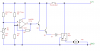
In the mean time, perhaps someone here can figure out the circuit from the article. The Poptronics article circuit uses two thermistors and a comparator driving a power transistor controlling a relay which switches the fan on and off. The temperature differential is set by a potentiometer (probably in series with one of the thermistors). I will attach the document text.
 

Attachments

  • poptronics-0601-article.zip
    4.7 KB · Views: 720
Last edited:
The author is one of our members. Dean, where are you?:p
If the name written was mistyped you'd be right. We don't have Dean Hurster in the forum.
 
Sounds like he put the two thermistors, R2 and R5, in a four resistor wheatstone bridge circuit with the two other resistors, R3 and R4 equal to the thermistor resistance at room temperature. You could put a pot in series with one of the fixed resistors to allow adjustment of the temperature trip point. The output of the bridge goes to a differential comparator circuit that controls the fan relay. You would also need a small amount of feedback from the output of the comparator to the + input for hysteresis to generate a differential between the turn-on temperature and the turn-off temperature.

For info on bridge circuits just Google "bridge circuits".
 
Controlling fan speed

Thank you, Crutschow. That helps a lot. (There is a diode in there somewhere and maybe a pull up resistor but I think I can find another circuit diagram to tell me where to put them.)

I am also interested in improving efficiency of the system by matching the fan consumption to the available heat in the panel. This would require setting the fan voltage higher when the difference between the panel and room air temperature is higher and visa versa when the difference is less. This would require removing the relay at the least and using a power transistor with output in the range of the fan (12VDC 5A, maybe 1A). As I understand it, the comparator is basically a difference switch more than a difference amplifier. Could it be replaced by an op amp circuit that produces an output that reflects the difference of the two input voltages thereby driving the power transistor to vary the fan voltage? (I think you can tell I'm not versed in this technology.) :)
I suspect that on-off switching is about as efficient as you can get. Analog control (such as you suggest) will be less efficient, because you waste considerable power in the driver. You could convert the analog signal to PWM first, but I doubt that would be more efficient than the simple on-off control scheme.
If others know otherwise, I'm sure I will hear about it.;)
 
You're probably right, Ron.

The purpose of the fan is to optimize the difference between the temperature of the air flowing over the solar collector and the temperature of the collector itself by supplying cooler room air at the optimum rate. If the fan runs too fast, the air doesn't have time to get heated up much so we're wasting electricity. If it's too slow the air gets heated up most of the way early on and for the rest of the air's trip through the panel, the collector can't contribute much additional heat and the extra heat radiates out through glazing. As you say, it seems better to have the fan run too fast than too slow.

It will take some experimenting to figure out how mach can be gained by slowing the fan when the room air temp and panel temp are closer in value. I can do that with the circuit that Dean designed and then if it seems worthwhile I can look into varying the fan speed automatically.
 
Last edited:
Need for a relay with 12VDC 5A fan?

With a 12VDC 5A fan, is there any reason to keep the relay or can we just switch the fan from the power transistor? Is the idea to use a low power transistor to drive the relay so the power loss of the transistor is minimized?
 
Last edited:
Transistor switch for fan

With a 12VDC 5A fan, is there any reason to keep the relay or can we just switch the fan from the power transistor? Is the idea to use a low power transistor to drive the relay so the power loss of the transistor is minimized?
You can certainly drive the fan with a transistor, such as a power MOSFET as long as the fan ground is common with your circuit ground. If you require isolation between the two grounds, then you must use a relay (mechanical or solid-state). The transistor just needs to have a sufficiently low on-resistance so its power dissipation is low when it's carrying five amps.
 
Sounds like he put the two thermistors, R2 and R5, in a four resistor wheatstone bridge circuit with the two other resistors, R3 and R4 equal to the thermistor resistance at room temperature. You could put a pot in series with one of the fixed resistors to allow adjustment of the temperature trip point. The output of the bridge goes to a differential comparator circuit that controls the fan relay. You would also need a small amount of feedback from the output of the comparator to the + input for hysteresis to generate a differential between the turn-on temperature and the turn-off temperature.

For info on bridge circuits just Google "bridge circuits".

The circuit description mentions Q2 ("Darlington power transistor") and Q1 (protected from the relay field collapse by a diode). Are they just the two parts of the Darlington pair or is "Q1" a typo and it should be "Q2"? Does anyone have a good guess as to the specs or possible part number(s) for these component(s)?

I am going to try to draw a schematic and post it here to see if my understanding is in the right ballpark.

- Scott
 
Last edited:
Proposed schematic

I just downloaded Tiny CAD and drew the attached diagram. Please critique:
  • Is the diode (D1) in the right way around? :)
  • Should the variable resistor (R3) be on the plus input or the minus input of the comparator?
  • What is a good value for the feedback resistor? (R6)
  • What would be the right power transistors (Q1 and Q2) to use for a 12V relay with a coil drawing 100mA or less?
  • Do we need a Darlington pair or would one transistor be enough to drive the relay?
Thanks,
Scott​
 

Attachments

  • FanControl.png
    FanControl.png
    5.2 KB · Views: 674
Last edited:

  • The protection diode needs to be across the coil, not in series (cathode to the plus relay connection, anode to the minus connection)

  • A thermistor resistance goes down with a temperature increase. Thus the way you have R3 connected will cause R2 to cause the comparator trip point to be when it is at a lower temperature than R5.

  • R6 needs to go to the + input for hysteresis, not the -. It's value depends upon how much difference you want between the fan off and on temperatures, and how much resistance change in R2 and R5 that corresponds to.

  • You need a resistor at the output of the LM139 to the +12V. The LM139 has an open collector output and can not source output current. 1k ohm would be a good value. Also add a 100 ohm resistor in series with the base (to provide a higher voltage delta for the hysteresis signal).

  • With this value of output resistor you would only need one transistor to drive a 100mA relay. But the relay coil should be placed in series between the +12V and the transistor collector (no other connection to the transistor collector). The transistor emitter then goes to ground.
 
You need a resistor at the output of the LM139 to the +12V. The LM139 has an open collector output and can not source output current. 1k ohm would be a good value.

The 1K output resistor for LM139 at +12V is too low a value. The current is +12mA.

The LM139 datasheet gives output Vsat @10mA at around 0.8V and is even higher at 12mA, so a relay drive transistor might not turn OFF properly.

I would recommend to use a 4K7 resistor instead.
 
Another design

I found a design (with a schematic) for an LM339/thermistor-based thermostat controlling a relay: **broken link removed** by Bill Bowden and have tried to adapt it as a differential controller along the lines of Dean's design. Bill's approach also uses a Wheatstone bridge with a variable resistor but it gangs two of the comparators and drives them with 5V instead of 12 with a Zener diode regulating the power.

I have attached both my updated version based on Dean's design, as interpreted by Carl and others here, plus my adaptation of Bill's design based on what I have learned from you all.

I would appreciate any corrections, advice and especially an explanation of the advantages and disadvantages of each approach.
 

Attachments

  • FanControlAlaDean.png
    FanControlAlaDean.png
    6.2 KB · Views: 491
  • FanControlAlaBill.png
    FanControlAlaBill.png
    7.8 KB · Views: 473
Last edited:
I apologize for not having seen this thread until now. I NEVER, if ever check my PMs because I never notice the little teensy message at the top of the opening page. There were five or so unread/unanswered PM in the box when I finally noticed that the PM section even existed. Shame on me! Now I need to grovel before the feet of a few folks.

Anyway, when the "Wheatstone bridge" comment popped up, I thought "Whaaaaaa?" but then I looked at the schematic and realized that I guess it was a bridge. It's funny how the original design was done as a simple comparator and two voltage dividers, but then when you put the dividers together, they are a bridge. Forest? Trees? Forest? Trees?

Anyway, the circuit is simple, using a 741 powered from a single-ended +12v supply. The inverting input is taken from the divider junction of a 10K resistor (tied to +12v) and a NTC 10K thermistor (one end grounded); the non-inverting input from a three-resistor divider, the thermistor grounded and tied to a 2K pot when then goes through a 9.1K resistor to +12v -- the input is connect between the pot and the thermistor. Both input are bypassed with 1µF caps to ground. The output drives the base of a TIP120 darlington power transistor through a 10K resistor, emitter of the TIP120 grounded, collector connected to a 12v relay coil (other end of coil to +12v). There's a diode across the coil, cathode to +12v. The pot adjusts for the desired temperature differential. Note that the circuit works on the DIFFERENTIAL and not the actual temperatures, so has a lot of applications. If you need wider differential control, you'llhave to diddle with the pot and 9.1K values. The thermistors are Radio Shack items (271-110A).

If I were the least bit competent in computerese, I'd scan and post the schematic. I hate computers.

Dean
 
I now realize why I didn't answer this item back in November. I never saw it because I never visit this section of the forum! Maybe I need to change that. The only reason I found it was because it was pointed out in a PM (which I also didn't notice back in November).

Dean
 
Hi,
after hours of searching i found this site, perfect!!.

This project for a Temperature differential switch was just what i was looking for.
Fairly new to electronics, but this should work well for the control of a pump in a solar water heater that i am experimenting with,(not that we get much sunshine in the U.K.)

E.G. as long as the water in the heated coils is higher than the water in the storage tank the pump will circulate.

Cheers.
 
Status
Not open for further replies.

Latest threads

Back
Top