Continue to Site

Welcome to our site!

Electro Tech is an online community (with over 170,000 members) who enjoy talking about and building electronic circuits, projects and gadgets. To participate you need to register. Registration is free. Click here to register now.

  • Welcome to our site! Electro Tech is an online community (with over 170,000 members) who enjoy talking about and building electronic circuits, projects and gadgets. To participate you need to register. Registration is free. Click here to register now.

Temp. controled self cut off(ua741+LM35+relay)

Status
Not open for further replies.

skulenov

New Member
Hello all,

i'm new to the forum but not new to electronics ;)

i have a problem and i have a feeling that it's something trivial but i just can't get through it! :p

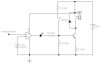
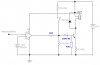
I'm trying to build a NiMH battery charger that is temperature controlled so when batteries get full they start to heat up, and when temperature rises to 35°C the LM35 sends 350mV to inverting input of uA741. The 741 in turn switches it's output from 14.3V(high) to 2V(low) and switches relay driving transistor off. Relay should break flow of current to 741 but that just don't happen! :confused:
It stays in on state, the pin 6(Output) of 741 is 14.3V and won't go down no matter what! maybe it just don't want to kill itself!? :D

I tested this part of circuit on a breadboard and it worked (i put a LED in place of relay and 741 and transistor worked ok and switched on and off depending on the state of '+' and '-' input levels of op-amp)

anyway, here's the schematic so please take a look and give me comments and any critics are welcomed!
 

Attachments

  • 741-switch.JPG
    741-switch.JPG
    19.4 KB · Views: 2,322
hi,
Your first problem is the LED in the output of the 741... How can the 741 output pull the transistor base low thru a 'reversed' biased LED [diode]

Remove the LED and try again.:)

EDIT:
Look at this image,,, the 741 has a poor specification.
 

Attachments

  • 741-switch.JPG
    741-switch.JPG
    19.5 KB · Views: 781
Last edited:
hey! thnx for reply eric! ;)
ok, i noticed error in picture: the Vtemp should be 180-400mV, not so relevant now...

about that LED: since output of 741 goes low, the LED becomes reverse biased and then the 4.7k pulls the base of transistor low... it worked on breadboard... but, ok, i'll go with your advice since i don't really know what else could be done... and, you spent some of your time to look at the sch and make your suggestion! ;)
ok now, i'll make these modifications and inform you how did it go...
 
i just saw a post that states that input voltage to either of 741 inputs should be 3v above -V, and in my single supply circuit the -V=0V so i guess that is the reason it doesn't react on input changes! maybe TL072? i have bunch of those... or NE5532? got few of them too...
there is one more solution in my mind... to amplify voltage coming from LM35, say 10 times...? that would yield 3.5V for 35°C... moreover, it can be done with just a single 8DIP since it contains two op-amps! :D one for amplifying and the other for comparator... am i theorizing in the right direction!? or is it just late and time for sleep... :D
 
Last edited:
ok, i just tested the modified circuit (removed LED and 12k resistor, placed 1k, 1n4148 and 47k as in sch) and it doesn't work. i suppose the reason is the constrain on input voltage range of 741 so i'm now going to replace 741 with tl072 and amplify voltage from lm35 10x and then send it to comparator(other half of tl072).

btw, relay holding current is now ~120mA which is too much, so it's going to a lower value.. about 60mA max.

my only objective is to completely switch off power to the charging and control circuit when preset temperature is achieved so that it can't turn on again once the batteries cool down.
 
The LM741 was first made in 1968. Some better OP amps have become available in the 40 years since then.

From the datasheet:-

Note 5: Unless otherwise specified, these specifications apply for VS = ±15V,
Input Voltage Range TA = 25°C MIN ±12 TYP ±13 V

What that means is that an LM741 can only detect the differences between voltages correctly if they are more than about 2 V above the 0V rail. They are really meant for ±15V supplies with ±10V input and output swing.

Your circuit puts the inputs of the LM741 at just 300mV, and the op amp simply doesn't work when you do that.

If you look at https://www.electro-tech-online.com/custompdfs/2009/01/LM741.pdf there is a circuit diagram. The input voltage needs to be more than the combined Base - Emitter voltages of Q1, Q7 and Q5 for those transistors to turn on and for the op amp to work.

There are so many better OP amps available. You want something that has an input voltage range that includes the negative supply.
 
ok, thnx for advice Diver!

i just found a way to make a signal voltage from LM35 higher! I just insert a LED in the ground lead of LM35 and it makes it's output voltage= Vled+Vtemp! That would say, for instance, when the temperature is 20°C the voltage referred to ground would be equal to 1.65v(LED)+0.2v(output of LM35)=1.85v.
I am now so embarrassed for not finding this earlier! oh!
Going to wire it all up and test it, and if it works i'll post entire sch here!
 
OK! :D

Everything went great! It turns out that 741(yeah, i stick with it) indeed reacts only when input voltages are ~2v above -V(that's 0v in this case).
So i did as i said in preceding post, putting a LED in ground lead of LM35 to pull up output voltage to Vout+1.65v. Now i think that i should go for more because now it won't react on temperatures below ~30°C but in my case it doesn't matter :p
In attached sch D1 is mounted close to BC548 (mine touches it) so that they are at almost same temperature so that the voltage won't change much.
I also put back LED that eric told me to remove because i like it when i can see the state of 741's output :D and it also drops the voltage enough so that the relay driver draws about 35mA which is enough to keep the relay on.
When the power is first applied relay is in off state and only the LM35 gets power.To start charging (which i didn't yet built) push-button must get pressed which applies enough current to base of driver transistor to turn it on and energize the relay coil which then closes contact and passes power to 741 and BC548. The trimmer resistor in base divider of BC547 serves to choose voltage at non-inverting input of 741 at which the circuit will cut-off power to itself and end charging process.
Only thing that is left to do is to build a constant current source to charge batteries.I'll use some NPN power transistor to do that since i have few of them laying around...it is only important to choose one that is capable of enduring 500mA of emitter current and that it doesn't get hot. As far as i know, Uce should be as low as possible so that the transistor itself dissipates as little power as possible.
Ok, now i'm going to that part... when it's finished i'll post it here ;)

btw, thank you eric and Diver for your opinions and advices!!!
 

Attachments

  • ch-temp-ctrl.JPG
    ch-temp-ctrl.JPG
    32 KB · Views: 750
If you're going to add the LED, you should put a capacitor in parallel with it, and you should use that as the negative for your reference voltage.

That way, variations in the LED voltage will not mess things up too much.

Or buy a better op amp.
 
If you're going to add the LED, you should put a capacitor in parallel with it, and you should use that as the negative for your reference voltage.

i didn't understand what you mean by this? I gather that you wanted to say i should connect junction of capacitor, LED and LM35 GND pin to the non-inverting input of 741? that way the non-inv. input of 741 would be at 1.65v which i think is not high enough to trigger it... or maybe it is?
Could you draw what you had in mind? i really don't get what you meant.sorry :)
 
Amplification of the output voltage of LM35

Hello guys ..
I am building a circuit that measures the temperature using LM35 and connected to ADC wich is connected to AT89s52 and LCD , but i am having a problem in the output voltage of LM35 , it is very small ! how can i amplify the voltage and know exactly the changing from the original voltage ??
Thank u very much
 
Status
Not open for further replies.

Latest threads

Back
Top