Continue to Site

Welcome to our site!

Electro Tech is an online community (with over 170,000 members) who enjoy talking about and building electronic circuits, projects and gadgets. To participate you need to register. Registration is free. Click here to register now.

  • Welcome to our site! Electro Tech is an online community (with over 170,000 members) who enjoy talking about and building electronic circuits, projects and gadgets. To participate you need to register. Registration is free. Click here to register now.

tda7240 amp project

Status
Not open for further replies.

aalauzier

New Member
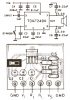
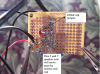
Hello again, I am starting a tda7240 amp build, and I have a few questions. When the finished circuit from the datasheet is built and plugged in, does the IC immediately start to warm up? I know that when it is working it gets hot, so is it normal for it to start to warm up right when power is applied? I will post the results of the first few tests, thank you.
 
If you did not build it with the recommended pcb design shown on the datasheet then the amplifier might be oscillating at a high frequency which makes a lot of heat.
The idle current is spec'd with a max of 120mA when the supply is 14.4V so it will dissipate a max heating of 1.73W but the typical idle heating is 0.94W.

Of course, it needs a heatsink that will dissipate about 11.5W. Then you will barely notice heating of only 1 or 2 watts.
 
I just attached a speaker to it and it did start oscillating, the speaker was humming and moving back and forth very slowly, and the tab got very hot, yet it made no music. I am using a 100K pot that I had lying around, one of the inputs from the input source goes into the first pin on the left, and the output going into pin 3 on the IC comes out of the middle pin on the pot, and the final pin on the pot is connected to ground. The other "common ground" pin on the input source is also connected to ground. Is there anything wrong with that? Do I just need to attack a heat sink to the IC? Help is always appreciated. Thank you.
 
Without seeing your schematic nor a photo of what you did it sounds like there are a few serious problems.
The center pin on the volume control should have a 1uF coupling capacitor in series to the pin 3 input of the TDA7240A amp.

This is the recommended schematic and pcb design shown on the datasheet:
 

Attachments

  • TDA7240.PNG
    TDA7240.PNG
    26.1 KB · Views: 1,989
There is a 1uF cap there, it is in the schematic so I forgot to mention it in the last post. Is the Heat sink another problem? Or can I wait until after testing to get one when I use it for long periods of time. Do I need the standby switch on when it is in use, because I do not have on in the circuit so far.Thank you for all of your help Audioguru.
 
Last edited:
Did you make the amplifier with the recommended pcb design?
Did you use all the parts shown on the recommended schematic?
Did you use shielded audio cable to connect the music source to the volume control and short wires from the volume control to the amplifier?

The temperature of the chip will heat 50 degrees C above the ambient temperature for each Watt of dissipation without a heatsink. So if its idle current is 120mA and the power supply is 14.4V then the dissipation is 1.73W and the chip temperature is 116 degrees C which is close to its max allowed temperature.
 
I will add a heatsink that I have, I did not use the ocb design because I do not yet have etching supplies, it is on a bread boad now, and I will put it on a protoboard. I used all of the recommended parts, but I only used shielded wire as the audio connector from my Ipod to an 1/8", then I used short wire to make the rest of the connections.
 
The TDA7240 and most other audio power amp ICs have plenty of internal gain at 3MHz. Then it will oscillate if you make it on a breadboard that is used only for DC and low frequency circuits.
If you carefully cut short all tracks on stripboard and place the parts very close together then it will work.
 
I moved it to a protoboard and fired it up, it idled at a regular temperature, but when I started playing the music, I could barely hear it, and the IC started heating up, but it is on a small heatsink. The 220uF cap attached to pin 6 is directly on the pin, because ther were no open holes, could that be the problem? Is the POT value too high at 100k? Do I need a smoothing cap along the + and - rails? if so, what value? Thank you for your time, Audioguru
 
I moved it to a protoboard and fired it up, it idled at a regular temperature, but when I started playing the music, I could barely hear it, and the IC started heating up, but it is on a small heatsink. The 220uF cap attached to pin 6 is directly on the pin, because ther were no open holes, could that be the problem? Is the POT value too high at 100k? Do I need a smoothing cap along the + and - rails? if so, what value?
You never told us the power supply voltage, nor the speaker's impedance.
Maybe the IC was damaged when it overheated when you tried it on the breadboard.
The 220uF cap is the supply bypass capacitor but its value is too low to be the only big bypass capacitor. For good bass the total of the filter capacitors should be 2200uF to 4700uf.
There is no negative rail, just the positive rail and ground.
The datasheet shows that the input resistance of the amplifier is 70k minimum so the volume control should be from 10k to 100k.
 
The input is a 12V wall wart, speaker is 8Ω, and the 220uf cap is in series with a .1uf cap, so I should add a bigger one? Thank you
 
The 220uf cap is supposed to be in parallel (not in series) with the 0.1uF cap. The wall-wart probably has a capacitor that is at least 1000uF.
With a total of 1220uF then very low frequencies will be reduced but maybe your speaker cannot produce very low frequencies.

With a 12V supply, the output power at clipping into an 8 ohm speaker is only about 6.4W. The wall-wart must be able to produce 12V at 833mA (a total of 10W) or more and double that for stereo.
 
Thank you, I will moce the 220 cap lead into the middle of the solder, and the wall wart is a 12V 1 amp, but I will look for a slightly larger one. I will try and replace the 220 cap with a 1000uf cap if it still does not work as well as it should. Thank you again
 
Last edited:
I tried moving the 220 cap lead and that made no difference, the speaker does oscillate slowly and buzz, I tried to add a 100uf smoothing cap along +and ground and it only sparked so I did not continue with that. What should I do? If you need a pic of it, i will take a few, just tell me what you want photographed, I am completely lost, help would be great. 4 of the caps are axial, and I have never used them before, so I looked them up online and saw that the dimple in one end marks the + end, so i put that lead coming from the IC into ground, are these backwards? They do not heat up so I think they are right. Help would be great because I have no idea what to do.
 
Modern electrolytic capacitors have a big arrow pointing to the negative wire which is ground in your circuit.
Take a clear photo of your circuit board and label (use Microsoft Paint program) the parts values.
 
These cap dont have many markings, like a regular cap has the big strip on it, these don't for some reason, so I checked online and found that a dimple on them was supposed to be the + leads. The speaker is a 50W 8Ω, 2 for $10, couldnt resist
 

Attachments

  • 100_3904.JPG
    100_3904.JPG
    1.3 MB · Views: 477
  • 100_3905.JPG
    100_3905.JPG
    1.3 MB · Views: 420
  • Screen shot 2010-09-17 at 10.07.43 PM.png
    Screen shot 2010-09-17 at 10.07.43 PM.png
    406 KB · Views: 427
Last edited:
more pics, realized a possible mistake of the speaker outputs, will move them
 

Attachments

  • Screen shot 2010-09-17 at 10.14.38 PM.png
    Screen shot 2010-09-17 at 10.14.38 PM.png
    379.9 KB · Views: 897
  • Screen shot 2010-09-17 at 10.18.06 PM.png
    Screen shot 2010-09-17 at 10.18.06 PM.png
    406.5 KB · Views: 859
  • Screen shot 2010-09-17 at 10.20.58 PM.png
    Screen shot 2010-09-17 at 10.20.58 PM.png
    402 KB · Views: 694
I just moved the spk. out wires and it works when no power is applied, at the strength of my ipod. Should it do that? because when I apply power it becomes staticy and distorted
 
I haven't seen axial electrolytic capacitors for about 35 years. Maybe yours are old and do not work anymore.
Look closely at the schematic and pcb design on the datasheet. C5, C6 and C7 are not polarized and are the shape of ceramic capacitors that are good for high frequencies so that the amplifier does not oscillate. Replace your electrolytic capacitors.
 
Status
Not open for further replies.

New Articles From Microcontroller Tips

Back
Top