Continue to Site

Welcome to our site!

Electro Tech is an online community (with over 170,000 members) who enjoy talking about and building electronic circuits, projects and gadgets. To participate you need to register. Registration is free. Click here to register now.

  • Welcome to our site! Electro Tech is an online community (with over 170,000 members) who enjoy talking about and building electronic circuits, projects and gadgets. To participate you need to register. Registration is free. Click here to register now.

Tapping into 24v ac/dc source

Status
Not open for further replies.

RFtinkerer

New Member
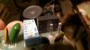
Does anyone know what this component is ? (to the right of the dip switch and behind the prongs) It has 24v AC going in the center and 24 v DC going out on the sides, but when I try to add a device to this power source I get a severe voltage drop. I've taken into account the resistance of the device and it just doesn't add up.
 

Attachments

  • 24v input.jpg
    24v input.jpg
    953.4 KB · Views: 188
Looks to me like a bridge rectifier.

JimB
 
Ditto, I see a full wave bridge rectifier. AC in center two terminals and DC out marked + and - on the outside terminals. Matter of fact the "prongs" you refer to look to be the AC input to the bridge.

Ron
 
Vout = V * R2 Vout= 24 * 7K Vout= 168,000 Vout= 5.79 v
R1 + R2 22K + 7K 29,000

for some reason I get 1.6 volts on my meter :meh:
 
If it says kbpc then its a bridge, fairly sure it is anyway.
If you look at a schematic for a bridge you'll see 4 diodes, you can test each one with a diode test that most meters have these days, you should get around 0.6v per diode, if ones high then it could be open, or maybe one is shorted.
 
What exactly are you trying to do? Exactly in detail? What is the AC voltage going into the bridge? What do you measure across the bridge + and - out?

Ron
 
Ok, I'm trying to use the 24 v AC supply from the bell wire on this garage door opener to power this**broken link removed** by dividing the voltage with resistors. But additionally I am having the same problem on a similar project using the same kind of receiver and a 9 volt battery. So , I'm thinking this is a power supply issue. Would a voltage regulator be a better way to go here ?
 
Yes a reg would be better, you need 10x the current through a resistive divider than that it supplies, and then voltage would change with load.
A 78 series reg is probably what you need.
 
the very first thing you have to do is change the AC to DC. You could have let out the magic smoke already since AC reverses it's polarity.
You will either have to half wave or full wave and filter. Full wave will give you about 33 V which is a lot to drop for a 12V supply. Half wave would be about 1/2 that.

So you MIGHT be able to get away with a zener diode regulator for 10 mA. See https://www.google.com/url?sa=t&rct...NWkdOsn8S1n6rxM85X7Yi9w&bvm=bv.86475890,d.eXY

Otherwise convert to DC and go with a DC-DC converter.
 
Ok thanks, the 78 series regulator worked on the one project. Although, I couldn't find a 33uf cap. anywhere locally. On to the next project !
 
Collect and scrounge dead equipment and use a hot air paint stripper to salvage the components off, you'll hardly be stuck again for something.
Oh yes 33uF is a fairly uncommon value, 22 and 47 are more popular.
 
Why do you need a 33uF electrolytic capacitor with a 78 series regulator? The datasheet shows a 0.33uF ceramic input capacitor and a 0.1uF ceramic output capacitor.
 

Attachments

  • 78xx voltage regulator.png
    78xx voltage regulator.png
    3.3 KB · Views: 143
Status
Not open for further replies.

Latest threads

New Articles From Microcontroller Tips

Back
Top