Continue to Site

Welcome to our site!

Electro Tech is an online community (with over 170,000 members) who enjoy talking about and building electronic circuits, projects and gadgets. To participate you need to register. Registration is free. Click here to register now.

  • Welcome to our site! Electro Tech is an online community (with over 170,000 members) who enjoy talking about and building electronic circuits, projects and gadgets. To participate you need to register. Registration is free. Click here to register now.

Tank filling circuit with relays if possible

Status
Not open for further replies.

djreiswig

New Member
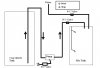
I am trying to build a circuit using relays to fill a tank. The tank will have two float switches. The lower float switch will control the amount of water going into the tank. The upper float switch will control the amount of concentrate going into the tank.

The water is controlled by a solenoid valve. The concentrate is controlled by a pneumatic pump with the air controlled by a solenoid valve, as well as a solenoid valve on the concentrate pipe to prevent siphoning.

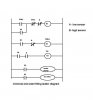
The process should be as follows: When the start button is pressed, if the lower level is not reached the water valve is activated and the tank fills with water. When/If the lower level is reached then the water valve is closed and the air valve opens and starts the pump and the concentrate solenoid valve opens. When the upper level is reached all valves close and the process stops. If the stop button is pressed at any time, all valves close and the process stops. If the process is stopped in this manner, when the start button is pressed again, the process needs to start in the correct part of the sequence.

I have a 110ACto 24DC transformer and several 4PDT relays that I would like to use, if possible. The float switches I have only have one set of contacts, and will function as NO or NC depending on which way they are installed.

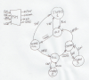
Attached is a sketch of my installation.
 

Attachments

  • Mix tank.JPG
    Mix tank.JPG
    23.5 KB · Views: 809
This is a consulting job. How much do you pay?
 
I thought maybe some kind individual on this board would help me come up with something. If not, I'll see if I can find another forum. I have some ideas, but I haven't quite come up with something that works the way I want.

Thanks.
 
So you need a Finite State Machine with four inputs, four outputs, and 7 states. This is tough to do with only relays. I would use Logic or a PIC. That is why I said it is a design job.
 

Attachments

  • FSM.png
    FSM.png
    437.1 KB · Views: 602
Last edited:
Tank filler

Relay logic -- cool.
I think this does what you described, but check it out. Seems like there will be quite a variation in the concentration if it is interupted.
 

Attachments

  • tank.GIF
    tank.GIF
    23.7 KB · Views: 618
...
I think this does what you described...

How does this remember the state it was in (so it can go back to that state) if it is interrupted with the STOP button?
 
Thanks for the circuit.

This doesn't do quite what I want. It looks like it turns both the water and concentrate on at the same time. I want them to turn on in sequence depending on what the level in the tank is. If the tank is below the low float then only the water should turn on. If the level is above the low float and below the full float then only the concentrate should turn on. This is how I will get my concentration to be correct.

Also, I see nothing in there to turn off the "Start" relay. It appears to be held on through it's own contacts with neither of the floats in between, so it will stay on until someone hits the stop switch.

I also would like to have a separate pump and valve turn on after the filling is complete and for 5 minutes or so to mix the tank.

I think I have something figured out for the filling (haven't built it yet), but I haven't come up with a way to automatically mix. This may have to be a separate circuit.
 
mixer

The start relay (latch) is there because the switches are only single throw. It is reset when stop is pushed because it no longer has 24 volts - Stop is normally closed and acts as a reset. As for where to start when interrupted. I think there are only 3 conditions: The water is below the lower switch in which case you fall thru the start relay to the water relay untill it is above the water switch. If it is above that switch but not full then water doesn't pick because the water switch is open and it falls thru to the concentrate relay. (I think there is a mistake here. The line to the water relay from the common of the start relay should go to the normally closed contact on the water relay not the normally open). In this case concentrate is added until the full switch opens. If it's full both the water low and full switch are open so nothing happens. The problem I see is when the tank is not all the way empty and someone starts it over with some concentrate still in the solution. Or it has been emptied to the mid point and gets restarted and gets to much concentrate. These were not a part of the problem but may be "a" problem. If it is I think you need more "stuff" to fix it. Does it matter?
Your right the start switch needs to be reset when the tank is full - one more relay. But are the mixture problems ok? If not how do you think they can be fixed?
 
Not worried at this point about the process being started before the tank is empty. I will be using this set up, so I just want something to automate the process a little. So I can make the determination to proceed and then hit a button and a batch is made. I guess some sort of float at the bottom of the tank would probably take care of this, but I think it is okay to ignore this "problem" for now.

Any ideas on how to incorporate the mixing into this circuit with some sort of timer? I don't have a timer yet, so that is open to suggestion.
 
Fixes/Timer

OK. Think it is ok now. But check me out.

Here is a link to a delay timer. I think it's about $13

**broken link removed**

ICM Controls Delay Timer - ICM105B
 

Attachments

  • tank.GIF
    tank.GIF
    28.7 KB · Views: 449
I think you're close. A couple of things. It seems like the Not Full relay will power up anytime the tank is not full. It takes a couple of months for the tank to get empty and ready for another batch. Probably not ideal. Also, the start relay doesn't shut off after the cycle is complete, unless the stop button is pressed. It would be nice to have all relays off after things are completed. Not sure if this is possible or not.

As for the mixing part of the cycle. I don't see that in your circuit. The timer you suggested won't work because it is only AC and I have 24VDC. How would I go about incorporating the mixing part into this circuit?

Thanks for your help.
 
djreiswig,

since you need the process only one time when the start button is pushed then stop and wait until its initiated again, its not so difficult for you to use relays for this job, see the attached ladder logic diagram, it shows how you have to wire the relays and its contacts to get the required operation.

hope i dont want to explain how it works, you have to wire the relays, even different voltage levels can be used.

if some relays are not having enough number of contatcs they can be miltiplied by an intermediate relay.

Edit: small mistake modified. for mixer, you have to use a timer and trigger it when the tank gets full, stop it after 5min.
 

Attachments

  • chemical filling ladder diagram.JPG
    chemical filling ladder diagram.JPG
    26.8 KB · Views: 11,908
Last edited:
Okay, I'm not sure my first post was clear on the setup. I have an image I can post if someone can tell me how.

The water supply is controlled by a NC solenoid valve. The pump for the concentrate is controlled by a NC solenoid valve controlling an air supply. (It's an air driven diaphragm pump) There is also a NC electric ball valve on the pipe from the concentrate pump to prevent the concentrate from siphoning after the pump shuts off.

The pump I will be using to mix the batch is also an air driven pump. It is controlled by another NC solenoid valve controlling an air supply. (This is a separate pump from the concentrate pump) It is also used to fill a smaller tank thorough a separate NC electric ball valve. I already have the transfer part figured out so I do not need help on that.

The power supply for everything is 24VDC. I have several 4PDT relays and Start and Stop buttons with various stackable contacts both NC and NO.

Here's how I see it working.
With the blend tank empty...I press start. The water valve opens and the tank fills with water. When the lower level switch is reached (it's about 2/3 of the way up the tank) the water shuts off. The pump air valve opens and starts the pump and the concentrate ball valve opens and allows concentrate to flow into the tank. When the upper level switch is reached (almost at the top of the tank) the pump shuts off and the ball valve closes. Now that the tank is full the mixing pump air valve opens and starts the mixing pump. The NC ball valve on the mixing pipe also opens to direct the liquid back into the top of the tank. This will also start a timer that will mix for 5 minutes. When the 5 minutes expires, the mixing pump shuts off and the ball valve closes. At this point everything is stopped. When the tank is emptied, the whole process can be started again by pressing the start button.

If the stop button is pressed at any time, all valves should close and everything should stop. If the start button is again pressed, the process should start at the correct point in the sequence depending on the state of the level switches. (i.e. if the lower level is not reached then add water. if the lower level is reached then add concentrate. if the upper level is reached then allow the mixing pump to start for the set time. concentrate should not be allowed unless the lower level is reached and water should not be allowed if the lower level is reached.)

mbarazeen,
Not sure I follow your diagram. I will probably have to build it to see if if works. I think you may have some extra valves that I do not have. Please check it against the above sequence and see if everything is there.
 
Last edited:
mbarazeen,
Not sure I follow your diagram. I will probably have to build it to see if if works. I think you may have some extra valves that I do not have. Please check it against the above sequence and see if everything is there.

it will work as you described. the mixing part is not included in my post. i will shortly post you including that function too. by the way which kind of timer you have? about interrupting the process in between, when it will be interrupted during mixing, the mixing cycle will restart from beginning only. the rest can be started where it was left.

about understanding the diagram its easy, i have used 3 relays R1, R2, R3, two push button switches (start, stop) and two sensors A,B.
you can see NC & NO contacts illustrated in the diagram,

start from beginning push the push button to start (one side of the diagram is ground and other side is power), it will initiate R1 and R1 will latch since its own contact is looped in parallel with push button. the same way you can go through one by one and see.. you can understand it fully.
 
I see waterpump and air valve on your diagram. I don't understand what these should be. I need a water valve, an air valve for the conc pump, a concentrate valve, and an air valve for the mixing pump and a valve for the mixing pipe. Could you clarify these on your drawing?

I don't have a timer for this project yet. What do you suggest? It needs to work with the 24VDC supply I have.

Thanks.
 
Mixer

Go back a couple of posts. The not full relay is only there to make up for the lack of a normally open contact on the not full switch. It is what turns the start relay off when the tank is full. So I think it all works as you described. The relay won't mind being on, but if it bothers you I think you can figure out how to turn the switch over and use the oposite contacts on the relay. I think you can add the time delay relay to some spare N/O contacts on the not full relay for the mixer. If you don't want the ac in the contacts google dc time delay relay. There you go all done.
 
Would you be so kind to modify your cool schematic to reflect the changes you suggested? I would be very appreciative.

Thanks.
 
Bubble

Here is the circuit with the timer. Good Luck!
 

Attachments

  • tank.GIF
    tank.GIF
    31 KB · Views: 550
Status
Not open for further replies.

Latest threads

New Articles From Microcontroller Tips

Back
Top