Continue to Site

Welcome to our site!

Electro Tech is an online community (with over 170,000 members) who enjoy talking about and building electronic circuits, projects and gadgets. To participate you need to register. Registration is free. Click here to register now.

  • Welcome to our site! Electro Tech is an online community (with over 170,000 members) who enjoy talking about and building electronic circuits, projects and gadgets. To participate you need to register. Registration is free. Click here to register now.

Tank Circuit Control

Status
Not open for further replies.

eduardo_uk

New Member
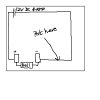
Ive been trying to work out a way of varying the speed of a tank circuit (a bell) want it to work from 5-12V (have a power supply that can vary voltage but cant be tuned whist the unit is running) have tried it using a potentiometer 4.7k and a 22k one, each time it seems to work fine but then when the wire in the potentiometer is at it's shortest it heats up and glows white hot. Cant seem to get hold of a rheostat that will do it any ideas as to how i can sort this problem out.
 
Need a schematic of what you are trying to do.
 
here it is this is very basic but i know enough to get by and repair but not enough to design circuits.. the power going in is 12V dc with a 4 Amp max. i know the bell cant be drawing very much current but using a potentiometer that is rates at 0.2W doesnt help.. i thought there might be a simple curcuit that can be built to do such a thing. or even a complex one just anything that would help would be most greatul
 

Attachments

  • potentiometer.jpg
    potentiometer.jpg
    25.6 KB · Views: 193
You need to measure the bell's current with 12V across it. Put an ammeter in series with the bell.
What do you mean, vary the speed?
 
in parallel to the Pot or the bell? wont doing that just increase the resistance of the pot? the pot works fine it's just at the point where the wire is shortest just before it goes to 0 resistance the wire inside gets extremely hot... is there no way around this... i know that the bell isnt drawing more than 3amps tops and maybe 4 at a split second peak surely there is a rheostat that can take that kind of current and if not it must have been replaced by something that can do the job more efficiently...
 
putting resistors in parallel decreases the total resistance but increases the amount of current/wattage that can flow through the resistors.

parallel resistors formula:

**broken link removed**

(Req = total resistance)

Note: only resistors in series increases the total resistance.

R1 + R2 + ... Rn = Rtotal

Say you have three 1Watt 30kOhm resistors in parallel, that means you have a 10kOhm 3Watt resistor.


paralleling the resistors with the bell may not have the effect that you are after. just parallel the resistors/pots together.
 
Last edited:
so say for instance if i have a 4amp current being drawn through a 22kohm potentiometer which is rated at 0.2A then what resistors would i need to add to make sure that the potentiometer could handle anything up to a max of 5amps actually 6amps max (just want to be safe)
 
If you add constant resistors(if this works cause it will be messy).You will only have control over the .2Amps max that your potentiometer can handle since you want even more resistance(for more current) the amount of control will further decrease.
 
Last edited:
how's about comming up with an answer instead of saying it wont work... i know it will work as ive seen designs where it has been done (just wishing id opened the boxes and taken a look at the circuit now ><) my thinking is by putting them in parallel with the potentiometer this will change the resistance but increase the load that it can take.. i just need someone to confirm it either way as it would work out fine. 22kohm is waay too much for what i need so it doesnt matter if adding resistors in will drop the total resistance so long as it stops the thing overheating... is there any other way of doing this?
 
and by overheating i mean at the point where the potentiometer is almost at 0 resistance but not quite.... by the way would a 25W 3A rheostat do the job?
 
Marvin.the.robot:
How are you going to adjust parallel pots? Put pulleys on the shafts, and connect them all together with belts?:rolleyes:

Eduardo_uk:
Does the resistor need to be easily adjustable (knob), or can you use a set and forget adjustable power resistor?
 
it has to be variable unfortunatly, like i said would a 25W 3A rheostat be the answer? ive built curcuits like this before for fan controlers and it has been fine so the only thing i can think that is different here is the current being drawn for a bell there surely cant be that much though this is why i signed up to this forum to see if i could get any answers
 
it has to be variable unfortunatly, like i said would a 25W 3A rheostat be the answer? ive built curcuits like this before for fan controlers and it has been fine so the only thing i can think that is different here is the current being drawn for a bell there surely cant be that much though this is why i signed up to this forum to see if i could get any answers
You didn't mention the rheostat's resistance. I was thinking of around 10 ohms, rated at 25-50 watts. It's difficult to say what you need unless you can tell us how much current the bell draws. Guessing is not really a good place to start a design from, even a simple one like this. Your rheostat might need to be as high as 100 ohms or more.
 
I would like to know what a tank circuit has to do with a bell, and what "change the speed" means.
 
change the speed means changing the speed at which the hammer strikes the bell.. ( jeeze cant you work that out????) ive told you what the current is MANY MANY TIMES the max it will be pulling is 4A but i want it to be able to withstand 6A just to be sure... anyway in the mean time ive worked it out and realised from this forum that no-one has a clue what they are talking about at all and everyone totally forgot that the bell would be producing an AC current of its own... so call experts.. more like the blind leading the blind... cya :(
 
Actually the bell will be producing nothing.

the switching done by the bell solenoid / switch combination will produce pulsed DC

(Edit)

Maybe you could explain why you need to change the hammer speed then we might know what you are talking about.

All the best.
 
Last edited:
change the speed means changing the speed at which the hammer strikes the bell.. ( jeeze cant you work that out????) ive told you what the current is MANY MANY TIMES the max it will be pulling is 4A but i want it to be able to withstand 6A just to be sure... anyway in the mean time ive worked it out and realised from this forum that no-one has a clue what they are talking about at all and everyone totally forgot that the bell would be producing an AC current of its own... so call experts.. more like the blind leading the blind... cya :(
I read every post about max current. You said the bell is drawing 3 or 4A max. That does not tell us what the actual current is. To calculate the resistance needed, we need to know the actual current.

You are one rude SOB. You can go piss up a rope. :mad:
 
Last edited:
Status
Not open for further replies.

Latest threads

Back
Top