Continue to Site

Welcome to our site!

Electro Tech is an online community (with over 170,000 members) who enjoy talking about and building electronic circuits, projects and gadgets. To participate you need to register. Registration is free. Click here to register now.

  • Welcome to our site! Electro Tech is an online community (with over 170,000 members) who enjoy talking about and building electronic circuits, projects and gadgets. To participate you need to register. Registration is free. Click here to register now.

Synchronous buck converter design

Status
Not open for further replies.

bryce1

New Member
I am trying to develop a circuit to convert 5-18Vdc, 100ma max to 0.4Vdc, 400ma. I am working on a synchronous buck converter design but I am finding limited resources on a discrete design. All of the buck converter IC's I found do not go low enough and have inadequate efficiency when they are even close. I have been toying with the idea of using the basic synchronous converter with a P and N channel fet. The problem is that I am trying to use a MSP430 microcontroller to drive the circuit. What would you reccomend for a gate driver for the upper P-channel fet? If you any other suggestions please put them in too.
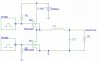
I am attaching a rough schematic for review.

Thanks
 

Attachments

  • buck.jpg
    buck.jpg
    31.3 KB · Views: 1,132
before going on, why do you need 0.4 volts?, that is effectively an analogue signal level NOT a power voltage rail

There is not enough volts there to start a diode conducting and the MAXIMUM impedance that your load could have is 160mOhms
 
Max impedance for the load would be 1ohm. Max power dissipation would be 160mW. The load is a thermoelectric cooler (peltier cooler).
 
EDIT OUT
 
Well, if you REALLY need to regulate at 0.4Vdc then you could try connecting an Op-Amp do the output and amplify the voltage from 0.4Vdc to say 2.5Vdc which would work with most switchmode regulators. Connect the output of the Op-Amp to the feedback line of your regulator, with appropriate op-amp gain control ofcourse.

I won't presume to know youre requirements, but would you be able to run your system on a linear regulator? Might be hell of alot easier connecting an Op Amp to a linear regulator and then going down to 0.4Vdc.

The support circuitry alone for your switching regulator (plus driving the fets themselves) might draw more power than a linear solution for this relatively low current system.
 
Glyph said:
Well, if you REALLY need to regulate at 0.4Vdc then you could try connecting an Op-Amp do the output and amplify the voltage from 0.4Vdc to say 2.5Vdc which would work with most switchmode regulators. Connect the output of the Op-Amp to the feedback line of your regulator, with appropriate op-amp gain control ofcourse.

I won't presume to know youre requirements, but would you be able to run your system on a linear regulator? Might be hell of alot easier connecting an Op Amp to a linear regulator and then going down to 0.4Vdc.

The support circuitry alone for your switching regulator (plus driving the fets themselves) might draw more power than a linear solution for this relatively low current system.

I have been considering offsetting the feedback pin on an off the shelf converter. I have some TI samples coming this week to try that.

I don't think a linear regulator would be near as efficient as a switching regulator could be. I'll have to look into it some more.

Thanks for the ideas.
 
bryce1 said:
What would you reccomend for a gate driver for the upper P-channel fet?

I just spent a long time learning how to do this with discretes and microcontrollers for a powerful low voltage Luxeon LED driver.

A capacitive coupler is ideal. Keep the PWM signal at 5v, ground referenced. Just use a small cap to couple the PMOS gate to the PWM, and put a 5.1V zener and a large resistor from gate to source to get proper bias on the cap. So with an 18V source, the cap will automatically charge to 13v while the PWM is on and the gate sees a 0 to 5v signal.

Make sure the freq response of the RC circuit is below the PWM freq. 100% (PWM=constant 0v) duty cycle must be avoided since vgs will decay as the cap charges up due to lack of a PWM signal. 0% (PWM=constant 5v) is fine since the cap will maintain the proper charge.

Use "logic level" MOSFETs on both legs. Also, really you can just use a diode in place of the NMOS. The 0.3v Schottkey diode drop is an efficiency hog since you've only got a 0.4v output, but it still doesn't amount to a lot at 400mA.
 
The bulk connection on P-ch should be connected to supply, not coil. There will be a parasitic diode from drain to source on each device cause by the bulk junction.

The issue is when the supply is 5vdc, where you have only 5v Vgs for P-ch. You have to get MOSFET's that have a relatively low Vgs control. With your low output current you can find MOSFET's that have a low enough Rs to get good efficiency with 5v Vgs. The two resistors is for turning off device. You have to be careful of input effective capacitance. The impact of input capacitance will depend on switching frequency. You can drive the P-ch gate with a current source NPN or N-ch driven from processor. This buffer must be there so the processor port is not subject to high end switcher input votage of 18vdc.

Current source to P-ch gate and gate to source resistors values must be low enough to charge and discharge the input capacitance in the required time at the frequency you are running the switcher at.
 
Last edited:
Use any good sync rec controller IC. For good efficiency at very low output voltages use several parallel N-FETs on the "low" side switch.
 
Status
Not open for further replies.

Latest threads

New Articles From Microcontroller Tips

Back
Top