I'm part way through a nightmare and hoping someone can brainstorm some ideas, as I've ran out. Right at the end of the prototype and an unexpected error shows up - the usual then!
I have two products which both use a NCP81166 sync buck controller. This has been deleted from OnSemi's website (no idea why) and I'm worried about availability long-term. It's sister chip is the NCP81155. The only difference between the two is the 66 supports 13V and the 55 is 5V. One of the circuits requires a long term backflow so I decided to do away with the bootstrap capacitor method and feed an externally generated 10v signal into the controller. As the max output is around 5v that leaves at least 5v to overcome the Vgs of the upper FET.
I've fed a 100% duty signal into the PWM input and the output saturates and goes to full voltage. Tick. I've fed a 0% duty signal in and the lower FET turns off, thus preventing discharge. Tick. This is the main reason why I've chosen these chips, they have diode emulation so work fine at low or zero duty loads where the input < output due to a capacitive load.
So far so good then.
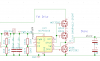
There are various feedback loops controlling when the controlled should buck, when it should backflow and so on, but I'll only focus on the basic buck one. It's a closed loop, voltage regulated via hysteretic feedback. Although I don't have spice models for the NCP81166 I've made equivalent circuits for it and the feedback circuit to test the principle. In the actual circuit one of the control loops is the output voltage read by a PIC16 comparator. I'm using the PIC16F1679 chip specifically, and the comparators on this are fast (perhaps too fast).
What actually occurs is the output is regulated perfectly, which suggests the feedback loop is working, but the current going through the lower FET is abnormal. With the output regulated at least 100mA is going through the bottom FET. I can see roughly on the oscilloscope the PWM being generated, although it's too random to gauge a pattern.
I'm considering that it could be:-
1. the comparator is switching way too fast and the sync controller can't keep up.
2. the low RDS FET (40mOhm) aren't enough for the sync controllers ability to turn on/off the FET at zero current through the inductor.
3. the inductor value is way too low (I've gone from 2.2uH to 10uH and it seems a tad worse).
4. I'm not bucking correctly, I should try a 1MHz square wave signal and turn this on/off based on the comparator value.
I have two products which both use a NCP81166 sync buck controller. This has been deleted from OnSemi's website (no idea why) and I'm worried about availability long-term. It's sister chip is the NCP81155. The only difference between the two is the 66 supports 13V and the 55 is 5V. One of the circuits requires a long term backflow so I decided to do away with the bootstrap capacitor method and feed an externally generated 10v signal into the controller. As the max output is around 5v that leaves at least 5v to overcome the Vgs of the upper FET.
I've fed a 100% duty signal into the PWM input and the output saturates and goes to full voltage. Tick. I've fed a 0% duty signal in and the lower FET turns off, thus preventing discharge. Tick. This is the main reason why I've chosen these chips, they have diode emulation so work fine at low or zero duty loads where the input < output due to a capacitive load.
So far so good then.
There are various feedback loops controlling when the controlled should buck, when it should backflow and so on, but I'll only focus on the basic buck one. It's a closed loop, voltage regulated via hysteretic feedback. Although I don't have spice models for the NCP81166 I've made equivalent circuits for it and the feedback circuit to test the principle. In the actual circuit one of the control loops is the output voltage read by a PIC16 comparator. I'm using the PIC16F1679 chip specifically, and the comparators on this are fast (perhaps too fast).
What actually occurs is the output is regulated perfectly, which suggests the feedback loop is working, but the current going through the lower FET is abnormal. With the output regulated at least 100mA is going through the bottom FET. I can see roughly on the oscilloscope the PWM being generated, although it's too random to gauge a pattern.
I'm considering that it could be:-
1. the comparator is switching way too fast and the sync controller can't keep up.
2. the low RDS FET (40mOhm) aren't enough for the sync controllers ability to turn on/off the FET at zero current through the inductor.
3. the inductor value is way too low (I've gone from 2.2uH to 10uH and it seems a tad worse).
4. I'm not bucking correctly, I should try a 1MHz square wave signal and turn this on/off based on the comparator value.