Continue to Site

Welcome to our site!

Electro Tech is an online community (with over 170,000 members) who enjoy talking about and building electronic circuits, projects and gadgets. To participate you need to register. Registration is free. Click here to register now.

  • Welcome to our site! Electro Tech is an online community (with over 170,000 members) who enjoy talking about and building electronic circuits, projects and gadgets. To participate you need to register. Registration is free. Click here to register now.

Switchmode PS + Schematic What do you think?

Status
Not open for further replies.

lemonyx

New Member
Thank you all EE guru's - for helping and taking the time to help. :D

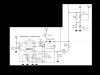
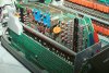
I have my Switchmode PS (thanks to you guy's) to power my 6 Tube Nixie Clock that I want to build. (see attached) and will be using this schematic (see attached) for making the board.

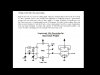
The initial power will be thru a regulated 12v, 1.5a wall wart, would I need to add this circuit to keep "Correct Time"? (ripple based time) Or a 1hz generator in the 4th attachment? (see attached) And where on the schematic would it go?

Please help me piece this together as I am not an EE by any means, but I can still design somewhat using Eagle Lite and diy PCB's @ home.

The Nixie tubes, the 74141's (coming from overseas) and the rest of the parts are locally. I've sampled in several of the Max771's and maybe they will send me some Max1771's as well (newer model). :rolleyes:

Thank you all.
 

Attachments

  • Clipboard03.jpg
    Clipboard03.jpg
    90.2 KB · Views: 193
  • nixieclock.gif
    nixieclock.gif
    116.2 KB · Views: 188
  • ripple-based-time.gif
    ripple-based-time.gif
    11.4 KB · Views: 187
  • Clipboard04.jpg
    Clipboard04.jpg
    163.8 KB · Views: 186
Here's a single supply 9v to 170v nixie supply based on a 555. You can almost get all the parts from Radio Shack. It's a shame that TTL is getting hard to find.

If it were me I'd cheat a little and use an old PIC cpu as a timebase. But hey a real purist would build the whole thing without any ICs.

https://www.hpmuseum.org/tech9100.htm
 

Attachments

  • nixie_supply.pdf
    86.9 KB · Views: 301
  • 9100nint.jpg
    9100nint.jpg
    83.3 KB · Views: 166
Bill

Thank you for the links. I might go that way except for the trim pot, I have no way of measuring voltage or know how to.

But lets say i did use the 555 PS, how would/could I incorporate it into the schematic? That small circuit from the 60hz input to the end of the "AND" gate, do i get rid of that?

thanks again for the link -
 
lemonyx said:
Bill

Thank you for the links. I might go that way except for the trim pot, I have no way of measuring voltage or know how to.

But lets say i did use the 555 PS, how would/could I incorporate it into the schematic? That small circuit from the 60hz input to the end of the "AND" gate, do i get rid of that?

thanks again for the link -

You really need the basic tools before any project. A mulitimeter is a must and are not that expensive, in many cases less than a soldering iron. Troubleshooting without a meter would be difficult.

60hz is only if you want an AC line clock (and don't live in a 50hz country). Clocks have been using the mains for ages and it's a pretty good (and cheap) way to drive a clock. There are ooodles of nixie clock schematics on the net, try google for nixie clock schematic

Bottom line you NEED some form of multimeter when you're building an electronic project ESPECIALLY when 130v is involved. You can get them for as little as $2 on ebay!!
 
Bill

The schematic is the 2nd attachment, back in the first post. I just need a little direction as to how to hook up a PS to this schematic and if there is any thing else that is needed.

On the 3rd and 4th attachment is a "clock generator" for a wall wart, which one would I need to use? Again I just need some direction on applying it to the schematic and making it work.

I found an old multi meter that still works, so I'm set there.
 
Last edited:
Status
Not open for further replies.

Latest threads

New Articles From Microcontroller Tips

Back
Top